
Power cabinet dehumidifying device

A power cabinet and power technology, applied in substation/distribution device housing, humidity control, non-electric variable control, etc., can solve the problems of dehumidifier noise, waste of electric energy, unsuitable for installation of dehumidifier, etc., to reduce air humidity , the effect of low power

Inactive Publication Date: 2016-05-11
STATE GRID CORP OF CHINA +1
View PDF7 Cites 4 Cited by
  • Summary
  • Abstract
  • Description
  • Claims
  • Application Information

AI Technical Summary

Problems solved by technology

However, due to the large three-dimensional space in the room where the cabinet equipment is installed, it is necessary to install a dehumidifier with a large power, which not only wastes electric energy but also produces a lot of noise when the dehumidifier is working, and some rooms where the power cabinets are located are not. Suitable for installing a dehumidifier

Method used


Image

  • Power cabinet dehumidifying device

Examples


Embodiment

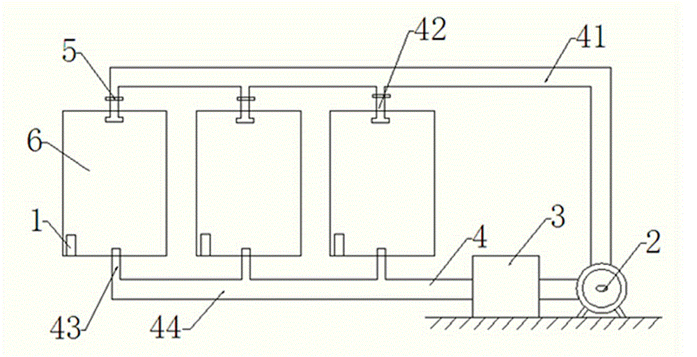
[0013] Embodiment: The power cycle unit is located near the power cabinet, and is connected to each power cabinet through the main circulation pipeline and the branch circulation pipeline, and each power cabinet is equipped with a humidity detector. When the humidity reaches the set value, the power is started. Circulation unit, at the same time turn on the switch of the branch pipeline, the air in the power cabinet enters the drying unit through the circulation pipeline, the moisture in the air is absorbed by the drying unit, and then circulates through the power circulation unit. The humidity detector is associated with the start switch of the power cycle unit and is associated with the corresponding branch pipe switch respectively. If the humidity in the power cabinet exceeds the standard, the power cabinet is dehumidified; or the humidity detector can also be set in the power cabinet assembly At the same time, the switch of each branch pipeline is connected at the same time...


PUM


Abstract

The invention discloses a power cabinet dehumidifying device comprising humidity detection units, a power circulation unit, a drying unit, a circulation pipeline and control switches. The power circulation unit is a closed circulation system, the outlet of the power circulation unit is connected with a main circulation pipeline and then connected with power cabinets through branch pipelines, the outlets of the power cabinets are connected with the main circulation pipeline through branch pipelines and then communicated with the drying unit, the drying unit is connected to the inlet of the power circulation unit, and the control switches are respectively arranged on the branch pipelines at the inlets of the power cabinets. The humidity detection units are installed in the power cabinets, are linked with a starting switch of the power circulation unit, and are linked with the control switches of the branch pipelines. By utilizing the power cabinet dehumidifying device, multiple power cabinets can be connected simultaneously, and the air humidity in the power cabinets can be effectively reduced without increasing the temperature in the power cabinets. Moreover, the power cabinet dehumidifying device has the advantages of low power, energy conservation and environmental protection.

Description

technical field [0001] The invention relates to a power cabinet of a power system, in particular to a dehumidification device for a power cabinet. Background technique [0002] The power cabinet is an important facility in the power system, and its safe operation is related to the normal operation of all related equipment, so its protection and inspection are also highly valued. If the power cabinet operates in a humid environment, it will bring hidden dangers to its safety. When the temperature is above 30°C and the relative air humidity is above 80%, it will cause condensation, which will cause corrosion of the terminals of the power equipment and reduce the Short circuit caused by poor insulation performance, resulting in undue power outages and losses. [0003] The common solution is to install a heater in the power cabinet to ensure that the air in the cabinet is dry, so that although the humidity in the cabinet is reduced, the temperature in the cabinet will rise, whi...

Claims


Application Information

Patent Timeline
IPC IPC(8): H02B1/28G05D22/02
Inventor 李文钊
Owner STATE GRID CORP OF CHINA
Learn More