Container sterilization method and container sterilization equipment

A technology for sterilization equipment and containers, which is applied in packaging sterilization, irradiation devices, nuclear engineering, etc., can solve problems such as pollution, and achieve the effect of prolonging operation time, reducing the stoppage of sterilization equipment, and preventing pollution.

Inactive Publication Date: 2017-09-01
HITACHI ZOSEN CORP
View PDF8 Cites 0 Cited by
  • Summary
  • Abstract
  • Description
  • Claims
  • Application Information

AI Technical Summary

Problems solved by technology

[0006] In addition, since the electron beam irradiation time for a container is 0.1 second, when the electron beam irradiation device generates an electric spark, it takes 0.1 to 0.2 seconds to restore the original irradiation output, so the container of the electron beam irradiation device that has been discharged may be directly Contamination of the sterilization chamber and filling device as equipment on the downstream side
At this time, the entire equipment must be stopped and cleaned.

Method used


Image

  • Container sterilization method and container sterilization equipment
  • Container sterilization method and container sterilization equipment
  • Container sterilization method and container sterilization equipment

Examples


Embodiment 1

[0029] Below, according to Figure 1 to Figure 5 Embodiment 1 of the electron beam container sterilization apparatus of the present invention will be described.

[0030] (equipment overview)

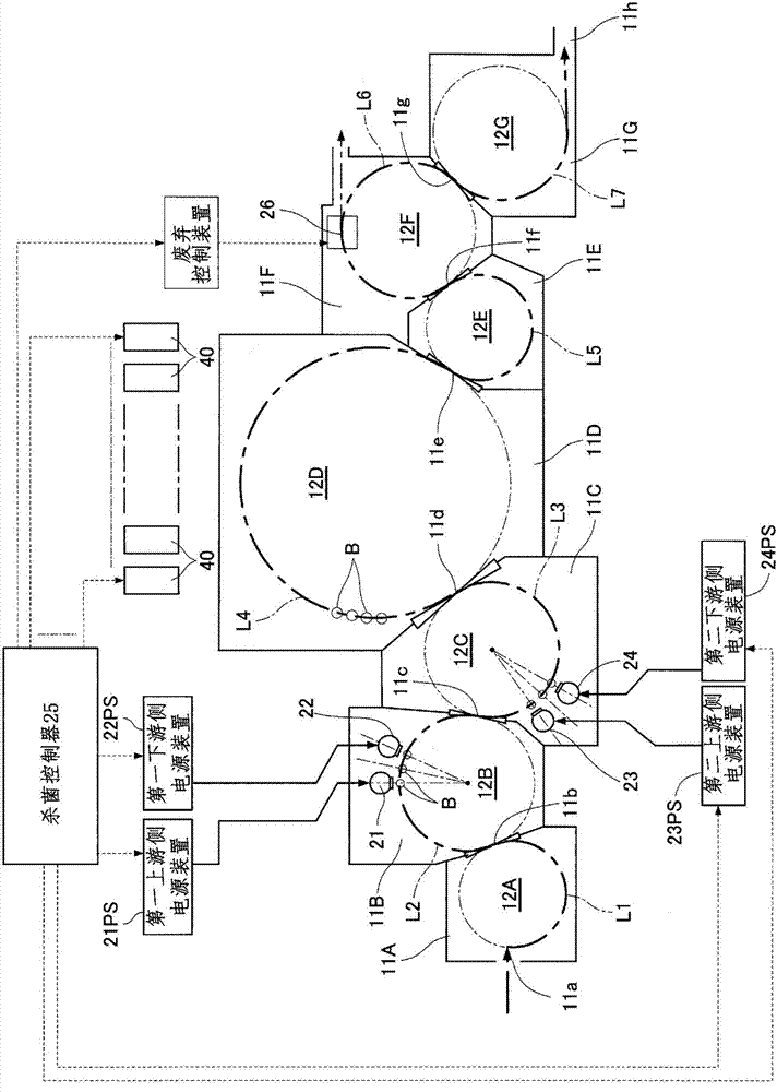
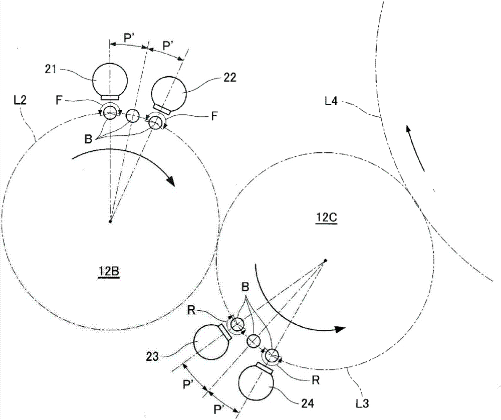
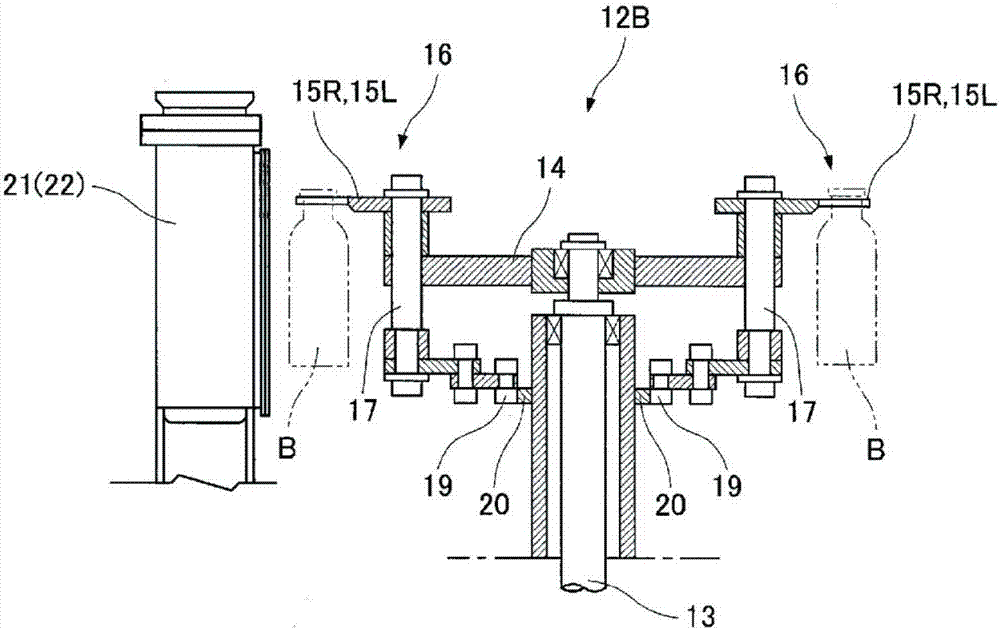
[0031] Such as figure 1 As shown, a plurality of first to seventh shielded rooms 11A to 11G are arranged in series via container inlets and outlets 11a to 11h. In the first to seventh shielded rooms 11A to 11G, first to seventh container transport devices 12A to 12G that transport containers B at a constant pitch P are installed, respectively.

[0032] The first shielded room 11A on the entrance side is formed with a circumferential container conveyance path L1 in which the containers B are conveyed by the first container conveyance device 12A. Electron beams (X-rays) are prevented from leaking to the container inlet 11a side by the first shielding room 11A.

[0033] The second shield room 11B and the third shield room 11C are outer surface sterilization rooms for sterilizing the outer...

Embodiment 2

[0056] Below, according to Image 6 with Figure 7 Embodiment 2 of the electron beam container sterilization apparatus of the present invention will be described. The electron beam irradiating apparatus of the above-mentioned embodiment 2 focuses on the fact that electric sparks are likely to be generated while the vacuum degree of the vacuum chamber is lowered, and is provided with a device for detecting the vacuum degree of each vacuum chamber 30 of the above-mentioned electron ray irradiating apparatuses 21 to 24 respectively. Vacuum sensor 21VS ~ 24VS. In addition, the same code|symbol is attached|subjected to the same part as 1st Embodiment, and description is abbreviate|omitted. For example, the above-mentioned "equipment outline" and "container conveying device" have the same structure as that of the first embodiment, so the description thereof will be omitted. In addition, since the "electron beam irradiation device" has the same structure except for the vacuum sens...


PUM


Abstract

Electron beams are irradiated to substantially identical sterilization surfaces on a container from a first upstream electron-beam irradiating device and a first downstream electron-beam irradiating device that are spaced with a predetermined distance upstream and downstream on a container carrier path. A sterilization controller controls the sum of electron beam outputs irradiated from the upstream electron-beam irradiating device and the downstream electron-beam irradiating device so as to allow sterilization on the sterilization surfaces of the container.

Description

technical field [0001] The present invention relates to a container sterilizing method and container sterilizing equipment in which a plurality of electron beam irradiating devices are arranged in line on a conveying path of containers. Background technique [0002] The container sterilizing equipment has two heads for irradiating electron beams to the object to be processed, and two filament power supplies for supplying power to the filaments of the two heads. The filament power supplies of each head are provided with switches, which are controlled according to the beam control signal. The predicted beam interruption threshold is compared with the actual beam current measurement value. When the beam current measurement value is below the beam interruption threshold, it is judged that the beam is interrupted. While maintaining the filament power of other heads , to stop power to the filament at the head where the beam was interrupted. [0003] Thus, in the multi-beam head t...

Claims


Application Information

Patent Timeline
Patent Type & Authority Patents(China)
IPC IPC(8): B65B55/08A61L2/08G21K5/04
CPCA61L2/087A61L2202/14A61L2202/23B65B55/08G21K5/02
Inventor 横林孝康
Owner HITACHI ZOSEN CORP
Why Eureka
Try Eureka