Printing and dyeing raw material mixing equipment based on synchronous mixing treatment

A mixing equipment and mixing treatment technology, applied in mixers, mixers with rotating containers, chemical/physical processes, etc., can solve problems such as difficult uniform mixing, color uniformity of printing and dyeing molding products, etc.

Active Publication Date: 2016-05-18
绍兴中漂印染有限公司
View PDF11 Cites 11 Cited by
  • Summary
  • Abstract
  • Description
  • Claims
  • Application Information

AI Technical Summary

Problems solved by technology

However, in the existing printing and dyeing raw material mixing process, it often adds the required primary color printing and dyeing raw materials in sequence. Because the printing and dyeing raw materials have a certain viscosit

Method used


Image

  • Printing and dyeing raw material mixing equipment based on synchronous mixing treatment
  • Printing and dyeing raw material mixing equipment based on synchronous mixing treatment
  • Printing and dyeing raw material mixing equipment based on synchronous mixing treatment

Examples


Embodiment 1

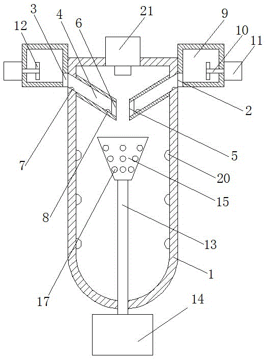
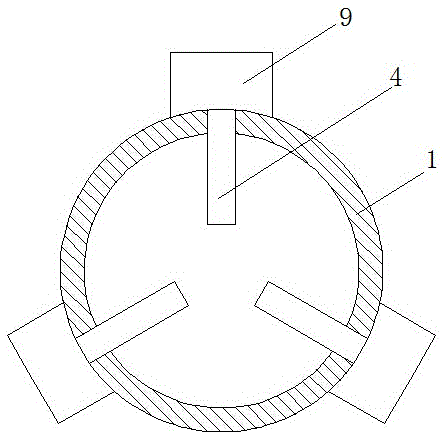
[0023] Such as figure 1 and figure 2 A kind of printing and dyeing raw material mixing equipment based on synchronous mixing treatment is shown, which includes a mixing cylinder 1, and three feeding ports 2 extending to the inside are arranged on the mixing cylinder 1, and the three feeding ports 2 It is rotationally symmetrical about the axis of the mixing cylinder 1, and a first control valve 3 is respectively arranged inside each feed port 2; Pipe 4, a plurality of feed pipes 4 are rotationally symmetrical about the axis of the mixing cylinder 1, and they all extend obliquely downward along the feed port 2, and each feed pipe 4 is away from the end of the side of the mixing cylinder 1 A metering port 5 is arranged at the top of the metering port 5, and a second control valve 6 is arranged at the corresponding position of the metering port 5; among the feed pipeline 4, a first flow meter 7 is arranged at a corresponding position on one side of the feed port 2, and the inle...

Embodiment 2

[0031] As an improvement of the present invention, such as figure 1 As shown, in each feeding box body 9, two feeding stirring blades 12 opposite to each other are arranged on the feeding stirring shaft 10, and the two feeding stirring blades 12 are turned 40 to 60° opposite to each other, which Through the structural setting of the feeding stirring blade, it can form a liquid flow that moves axially along the stirring shaft, so that the primary color dye in the feeding box can form a liquid flow moving toward the feeding port, and the feeding efficiency can be significantly improved. improve.

[0032] The remaining features and advantages of this embodiment are the same as those of Embodiment 1.

Embodiment 3

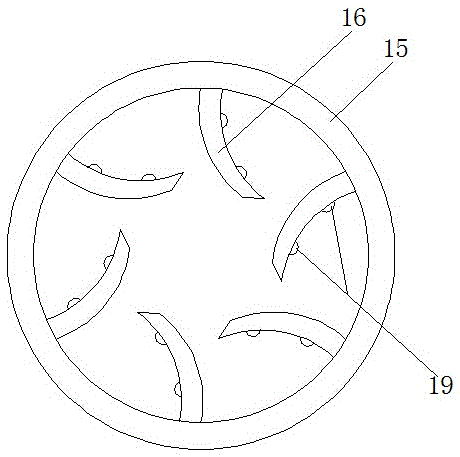
[0034] As an improvement of the present invention, such as Figure 4 As shown, in the outer wall of the stirring tank 15 , the upper end of each discharge hole 17 is provided with a deflector 18 , and the deflector 18 adopts an arc structure bent toward the upper end of the mixing cylinder 1 . With the above technical scheme, it can ensure that the dye thrown from the discharge hole moves towards the bottom of the mixing cylinder under the action of the deflector, so as to prevent the dye from being thrown onto the inner wall of the mixing cylinder, resulting in waste of raw materials and waste of cleaning. inconvenient.

[0035] The remaining features and advantages of this embodiment are the same as those of Embodiment 2.


PUM


Abstract

The invention discloses printing and dyeing raw material mixing equipment based on synchronous mixing treatment, which comprises a mixing barrel, wherein three feeding ports extending into the mixing barrel are arranged on the mixing barrel, the three feeding ports are spirally symmetric relatively to the axis of the mixing barrel, and each feeding port is internally provided with a first control valve; and the three feeding ports are respectively connected with a feeding pipe extending toward the axis of the mixing barrel. According to the printing and dyeing raw material mixing equipment adopting the technical scheme, through the arrangement of the three feeding ports in the mixing barrel, three primary color dyes can be fed and mixed synchronously, so that the uniformity of color of the molded dyes is more ideal; according to the printing and dyeing raw material mixing equipment based on synchronous mixing treatment, in the mixing process of printing and dyeing raw materials, three primary color printing and dyeing raw materials can be fed and mixed synchronously, so that the mixing uniformity is obviously improved.

Description

technical field [0001] The invention relates to a printing and dyeing raw material processing device in the printing and dyeing production process, in particular to a printing and dyeing raw material mixing device based on synchronous mixing processing. Background technique [0002] The quality of dyes used in printing and dyeing production is one of the important factors that directly affect the effect of printing and dyeing products. Existing dyes, especially dyes with special color matching, often need to mix different printing and dyeing raw materials using three primary colors according to a certain ratio in order to achieve the required color. However, in the existing printing and dyeing raw material mixing process, it often adds the required primary color printing and dyeing raw materials in sequence. Because the printing and dyeing raw materials have a certain viscosity, the printing and dyeing dyes mixed in the above way often appear in the mixing container. , maki...

Claims


Application Information

Patent Timeline
IPC IPC(8): B01F9/10B01F15/04B01F15/06B01F15/02
CPCB01F29/31B01F29/40113B01F29/4032B01F29/80B01F35/71805B01F35/883B01F35/95B01F35/93B01F2035/99B01F2101/30
Inventor 李娟
Owner 绍兴中漂印染有限公司
Why Eureka
Try Eureka