Welding wire guiding, conveying and detecting device

A welding wire guide and detection device technology, applied in the direction of optical device exploration, welding accessories, etc., can solve the problems of high misjudgment rate, poor reliability of limited detection signals, etc., to achieve low production cost, avoid welding equipment malfunction, avoid Effects of Welded Parts Scrap Problem

Inactive Publication Date: 2016-05-18
SHANDONG PENGXIANG AUTOMOBILE
View PDF9 Cites 0 Cited by
  • Summary
  • Abstract
  • Description
  • Claims
  • Application Information

AI Technical Summary

Problems solved by technology

[0004] The purpose of the present invention is to overcome the deficiencies of the above-mentioned prior art, and provide a welding wire guide transmission detection device; mainly to solve the problems that the existing welding wire detection device has limitations in use, poor detection signal reliability, and high misjudgment rate

Method used


Image

  • Welding wire guiding, conveying and detecting device
  • Welding wire guiding, conveying and detecting device

Examples


Embodiment 1

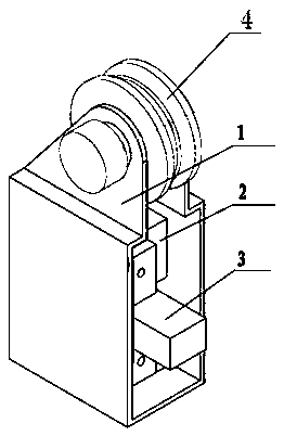
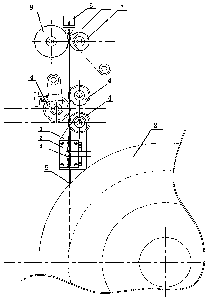
[0012] Example 1, see figure 1 , 2 , according to the design requirements, processed into accompanying bracket 1, welding wire guide block 2 and U-shaped photoelectric sensor 3; When the wire device correction wheel 4 slides axially, it can drive the accompanying bracket 1 to slide axially, and the accompanying bracket 1 can also do radial swing with the input angle of the welding wire 5; the welding wire guide block 2 is an insulator, and the welding wire guide block 2 has a welding wire guide hole , the aperture is different according to the diameter of the welding wire 5, on the welding wire guide block 2 there is a mounting groove and a mounting hole matched with the U-shaped photoelectric sensor 3, and there is a through hole for detection at the intersection of the mounting groove position and the welding wire guide hole; the welding wire The guide block 2 is installed in the accompanying bracket 1, and then the U-shaped photoelectric sensor 3 is positioned through the ...


PUM


Abstract

The invention discloses a welding wire guiding, conveying and detecting device. The welding wire guiding, conveying and detecting device is characterized in that a follow-up support (1) is arranged in a wire feeding device of a welding machine, and the follow-up support (1) slides axially and swings radially along with a rectifying wheel shaft of the wire feeding device; a welding wire guiding block (2) is arranged on the follow-up support (1); a U-shaped photoelectric sensor (3) is arranged on the welding wire guiding block (2). By the adoption of the welding wire guiding, conveying and detecting device, the welding wire detection of automatic welding equipment is achieved, and the problems that welding parts are scraped and misoperation of the welding equipment occurs due to the fact that welding wires are run out are solved. In addition, the welding wire guiding, conveying and detecting device has the advantages of being small in size, low in weight, reliable in detection, good in universality, simple in structure and low in production cost.

Description

Technical field: [0001] The invention relates to welding equipment, in particular to a welding wire guide transmission detection device. Background technique [0002] In the traditional welding process, the welding wire comes out of the wire feeding barrel or reel, passes through the wire feeding device, and then enters the welding torch for welding. There is no welding wire detection device in this process. When the welding wire is used up or broken, the welding wire cannot be replaced in time, resulting in Many workpieces have welding defects due to poor welding; for welding equipment with current tracking, it may sometimes cause malfunction of the welding equipment and damage the welding equipment. [0003] At present, there are also some welding wire detection devices, but they can only be applied to welding equipment that uses a specific wire feeding container of a wire feeding barrel or a wire feeding reel, and are not universal; in addition, the existing welding wire ...

Claims


Application Information

Patent Timeline
Patent Type & Authority Applications(China)
IPC IPC(8): B23K9/32G01V8/10
CPCB23K9/32G01V8/10
Inventor 于涛李曙光孙序志赵有正许军邹民马京帅
Owner SHANDONG PENGXIANG AUTOMOBILE
Why Eureka
Try Eureka