
Control method for switching working points of range extender

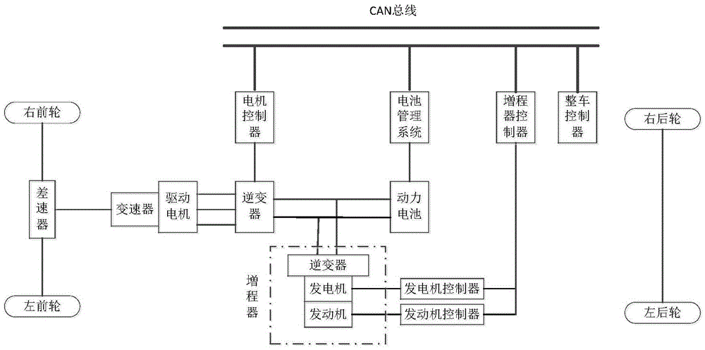
A control method and a technology of a range extender, which are used in transportation and packaging, motor vehicles, hybrid vehicles, etc., can solve problems such as increasing the complexity of the structure, and achieve the reduction of working noise, simplification of the structure, and reduction of rotational speed overshoot. Effect

Inactive Publication Date: 2016-05-18
JILIN UNIV
View PDF8 Cites 26 Cited by
  • Summary
  • Abstract
  • Description
  • Claims
  • Application Information

AI Technical Summary

Problems solved by technology

Although this solution can reduce the start-stop vibration and noise of the engine generator, it increases the complexity of the structure

Method used


Image

  • Control method for switching working points of range extender
  • Control method for switching working points of range extender
  • Control method for switching working points of range extender

Examples


Embodiment 1

[0082] Vehicle status data at the current moment:

[0083] Take the target power P of the range extender target is 30Kw, the current actual speed of the range extender n act It is 2400rpm, and the working point is switched to set the speed n diff 300rpm.

[0084] The judgment steps are as follows:

[0085] Step 1. Obtain the target power P of the range extender target ;

[0086] The range extender controller obtains the target power of the range extender as 30Kw through CAN bus signal transmission according to the control requirements of the vehicle controller;

[0087] Step 2. Obtain the target speed n of the range extender target and target torque T target ;

[0088] According to the optimal fuel consumption rate curve of a certain engine, the target power 30Kw on the engine’s optimal fuel consumption rate curve corresponds to a speed of 2500rpm and a torque of 114.6Nm, which are respectively taken as the target speed n of the range extender target and target torque...

Embodiment 2

[0097] Vehicle status data at the current moment:

[0098] Take the target power P of the range extender target is 37Kw, the current actual speed n of the range extender act It is 2400rpm, and the working point is switched to set the speed n diff 300rpm.

[0099] The judgment steps are as follows:

[0100] Step 1. Obtain the target power P of the range extender target ;

[0101] The range extender controller obtains the target power of the range extender as 30Kw through CAN bus signal transmission according to the control requirements of the vehicle controller;

[0102] Step 2. Obtain the target speed n of the range extender target and target torque T target ;

[0103] According to the optimal fuel consumption rate curve of a certain engine, the target power 37Kw on the engine’s optimal fuel consumption rate curve corresponds to a speed of 3000rpm and a torque of 117.8Nm, which are respectively taken as the target speed n of the range extender target and target torque...


PUM


Abstract

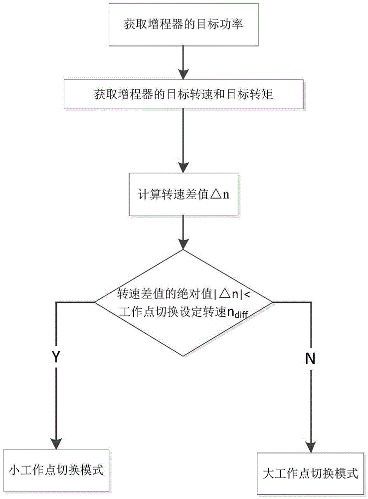
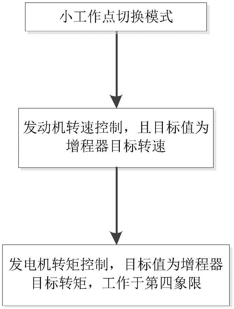
The invention relates to the technical field of new energy automobiles, in particular to a control method for switching working points of a range extender. The control method includes the following steps that 1, the target power P target of the range extender is obtained; 2, the target rotation speed ntarget and the target torque Ttarget of the range extender are obtained; 3, the rotation difference value delta n of the range extender is calculated; 4, in a range extender controller, whether the absolute value of the rotation speed difference value delta n of the range extender is smaller than the set rotation speed ndiff of working point switching or not is judged, and if yes, the working point switching process of the range extender enters a small working point switching mode; if not, the working point switching process of the range extender enters a large working point switching mode. According to the control method for switching working points of the range extender, in the working point switching process of the range extender, a system make a response rapidly, rotation speed excessive adjusting can be reduced, torque impact and work noise are lowered, the service life of the range extender is prolonged, and it is guaranteed that the range extender is simple in structure.

Description

technical field [0001] The invention relates to the technical field of new energy vehicles, in particular to a control method for switching operating points of a range extender. Background technique [0002] Extended-range electric vehicles have become the best choice for the transition to pure electric vehicles due to their performance advantages of less fuel, low emissions, and long driving range, and have broad market prospects. Among them, the range extender is a key component of the range-extended electric vehicle, which consists of an engine, a generator and its inverter, and the generator has both electric and power generation functions. [0003] When the power battery is fully charged, the range extender is turned off, and the vehicle is in pure electric working mode. When the power of the power battery is insufficient, the range extender is turned on, and the range extender tracks the target power demand, which is used to assist in driving the vehicle, and the vehi...

Claims


Application Information

Patent Timeline
Patent Type & Authority Applications(China)
IPC IPC(8): B60W20/40B60W20/10B60W10/06B60W10/08
CPCB60W10/06B60W10/08B60W20/10B60W20/40B60W2510/06B60W2710/0644B60W2710/081Y02T10/62
Inventor 初亮孙成伟赵迪高博王祎石求军张永生姚亮李文惠
Owner JILIN UNIV
Learn More