Remotely-controlled waterborne rescue device

A rescue device and remote control technology, which is applied in water rescue, ships, ship safety, etc., can solve problems such as limited use conditions and scope, inability to apply in batches, and inability to perform as expected, so as to save rescue time and have a simple structure , the effect of large working radius

Inactive Publication Date: 2016-05-18
NORTHWESTERN POLYTECHNICAL UNIV
View PDF7 Cites 17 Cited by
  • Summary
  • Abstract
  • Description
  • Claims
  • Application Information

AI Technical Summary

Problems solved by technology

In the patent 88105896.3, a "water rescue device" is disclosed. Although this rescue device solves the problem of rapid inflation and no need to inflate in advance, its application range is relatively limited, and it still cannot exert the expected effect when encountering large waves.
In the invention patent 200910071913.1, a "wired control water rescue device" is proposed. This water rescue device can be effective in the environment of relatively large wind and waves, but the wired control is connected by ropes for traction, the use conditions and range are limited, and it is not convenient to carry , cannot batch serve apps
Similar rescue devices still have great limitations in some aspects, so it is necessary to design a water rescue device that is quickly inflated, easy to carry, and has a wide range of application environments.

Method used


Image

  • Remotely-controlled waterborne rescue device
  • Remotely-controlled waterborne rescue device
  • Remotely-controlled waterborne rescue device

Examples


Embodiment Construction

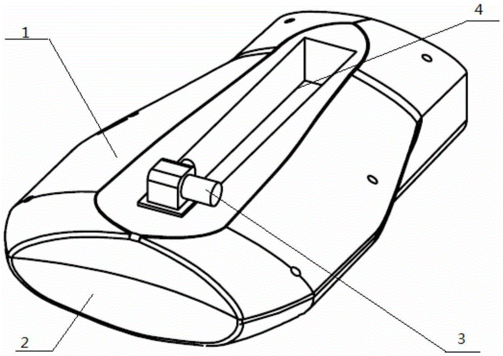
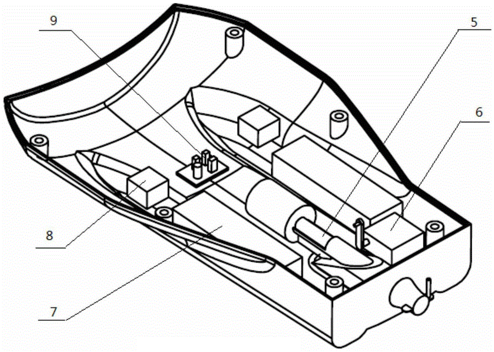
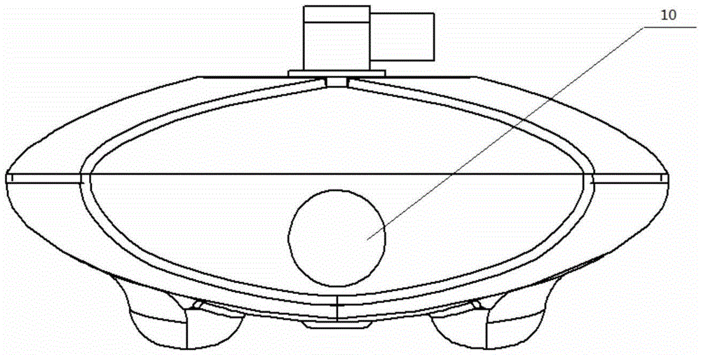
[0021] The present embodiment is a remote-controlled water rescue device.

[0022] See attached figure 1 , figure 2 , image 3 In this embodiment, the remote-controlled water rescue device is composed of a rescue device, a remote controller, and a life buoy. The rescue device includes an upper casing 1, a lower casing 2, a water pump 3, a carrying groove 4, a pump jet thruster 5, a steering gear 6, a battery 7, an electronic speed controller 8, a signal receiver 9, and a camera 10. The housing 1 and the lower housing 2 form a loading platform. The upper housing 1 and the lower housing 2 are sealed by rubber parts, and the inner space is sealed to carry electronic and mechanical components. The upper housing 1 and the lower housing 2 are fixed and installed by bolts. . A carrying groove 4 is arranged along the central axis of the top of the upper housing, and the water pump 3 is installed on the front end of the carrying groove 4, and an inflatable life buoy is placed in t...


PUM


Abstract

The invention discloses a remotely-controlled waterborne rescue device which is composed of a rescue device and a remote controller, wherein the rescue device is provided with a life buoy capable of being inflated quickly; a pump-jet propulsor of the rescue device is positioned at the rear part in a shell, and a tail pipe passes through a round hole in the rear end wall of the shell to extend to the outside; the pump-jet propulsor is connected with an accumulator through an electronic speed regulator so as to supply power, and the electronic speed regulator receives a control signal of a signal receiver to regulate the speed of the pump-jet propulsor so as to control the navigational speed; a steering engine is connected with the signal receiver to receive a control instruction sent by the remote controller to change the direction of the tail pipe of the pump-jet propulsor so as to control the navigational direction of the waterborne rescue device; and the remote controller is provided with a navigational direction and navigational speed control rocker for transmitting navigational direction and navigational speed control instructions, and target feedback information is searched through a camera at the front end of the rescue device. The rescue device is simple in structure and large in operation range; the remote controller is flexible in operation and controllable in recovery; and when the rescue device sails to a target falling into water, a trigger switch is controlled by the remote controller to inflate the life buoy so as to rescue people falling into water.

Description

technical field [0001] The invention relates to the technical field of water rescue equipment, in particular to a remote-controlled water rescue device. Background technique [0002] At present, common water rescue equipment includes a rope throwing device, a throwing type life buoy and a lifesaving throwing device. Although the rope throwing device and the throwing lifebuoy are simple in structure, their application range is small, and the throwing lifebuoy needs sufficient air for backup before launching. Throwing device needs professional operation, and safety is poor. Both the throwing type life buoy and the lifesaving throwing device are greatly affected by the environment and operator restrictions, and the throwing accuracy is not high. [0003] In recent years, the research and production of water rescue equipment have developed rapidly, and there are many reports about water rescue equipment. In the patent 88105896.3, a "water rescue device" is disclosed. Although...

Claims


Application Information

Patent Timeline
Patent Type & Authority Applications(China)
IPC IPC(8): B63C9/03B63C9/15
CPCB63C9/03B63C9/155B63C2009/035
Inventor 杜向党李芳陈晓郑丹丹孙思卿安徽王茁茁
Owner NORTHWESTERN POLYTECHNICAL UNIV
Why Eureka
Try Eureka