
A device for balancing and suspending a burner with a double constant force spring hanger

A technology of constant force springs and spring hangers, which is applied in the direction of using a variety of fuel combustion, combustion methods, combustion types, etc., can solve the problems of inability to use and directly arrange constant force spring hangers in parallel, and achieve reliable suspension, The way of arranging inclination and suspension is flexible and changeable, and the effect of solving the difference of expansion

Active Publication Date: 2018-03-23
SHANGHAI BOILER WORKS
View PDF5 Cites 0 Cited by
  • Summary
  • Abstract
  • Description
  • Claims
  • Application Information

AI Technical Summary

Problems solved by technology

This typical structure makes the suspension system face two major difficulties: one is that the intervals between the groups of the inclined burners are very small, and it is impossible to use the method of separately arranging constant force spring hangers for each group of inclined burners for suspension ; Second, considering the stability and safety of the inclination burner, two hanging points must be set on it. Considering that the principle of parallel connection of constant force spring hangers is that the specifications (including the length of the hanger) should be the same, there is no way to directly connect them. Parallel arrangement of constant force spring hangers with identical specifications

Method used


Image

  • A device for balancing and suspending a burner with a double constant force spring hanger
  • A device for balancing and suspending a burner with a double constant force spring hanger
  • A device for balancing and suspending a burner with a double constant force spring hanger

Examples


Embodiment 1

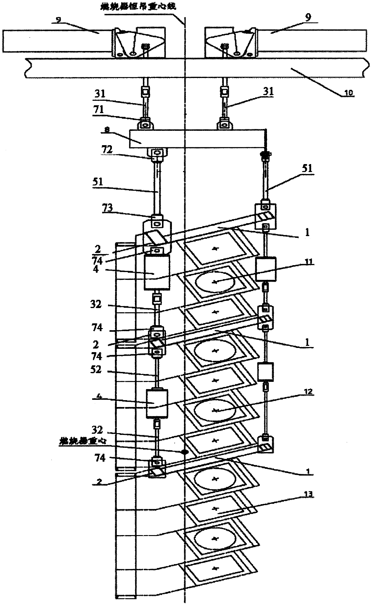
[0028] Such as figure 1 Shown is the structural schematic diagram of the double constant spring hanger balance suspension three-stage hanger type tilt angle burner in Example 1. The double constant spring hanger balance suspension three-stage hanger type tilt angle burner It includes a balance hanging beam 8, two constant force spring hangers 9 and a main burner. The main burner is arranged from top to bottom in a first group of inclination burners 11, a second group of inclination burners 12 and The third group of inclination burners 13 is formed, and the minimum distance between adjacent groups of inclination burners is 241mm. The three sets of inclination burners have slightly different structures, but all form an angle of 22° with the horizontal plane.

[0029] A hanger 1 is provided on the top of each group of angle burners. The angle between the hanger 1 and the horizontal plane is consistent with the inclination angle of the inclination burner. The two constant force spri...

Embodiment 2

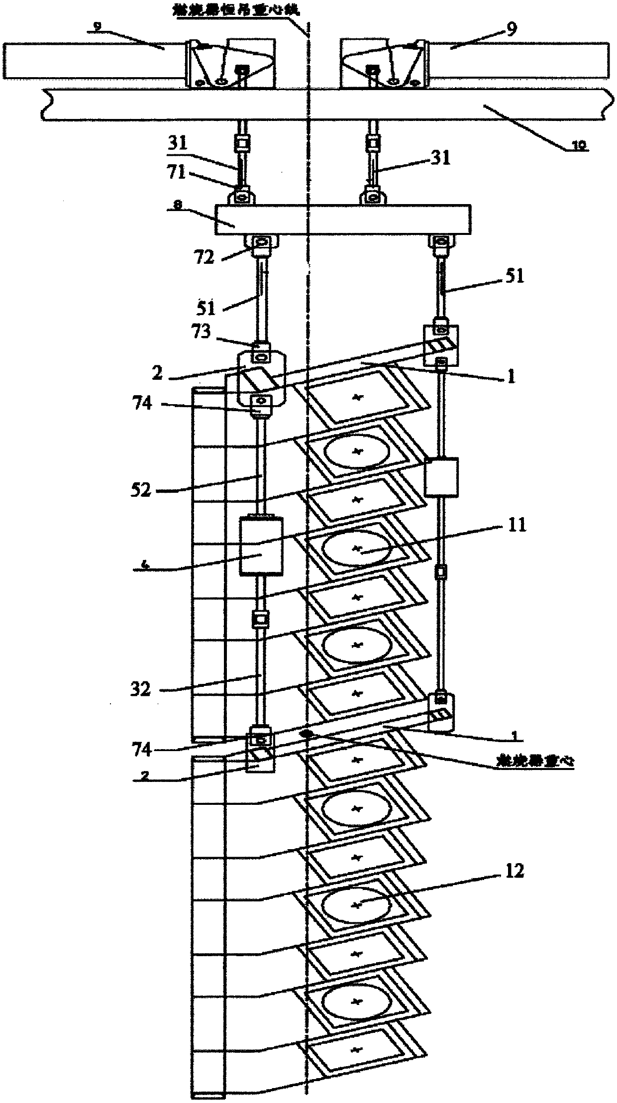
[0037] Such as figure 2 Shown is the structural diagram of the double constant spring hanger balance suspension of the two-stage hanger type tilt angle burner in embodiment 2. The double constant force spring hanger balance suspension two-stage hanger type tilt angle burner includes a balance suspension beam 8, two constant force spring hangers 9 and a main burner, the main burner is from top to bottom The first group of inclination angle burners 11 and the second group of inclination angle burners 12 are arranged in sequence below. The minimum distance between adjacent groups of inclination angle burners is 260mm. The two groups of inclination angle burners have slightly different structures, but they are both in line with the horizontal plane. Form an angle of 25°.

[0038] A hanger 1 is provided on the top of each group of angle burners. The angle between the hanger 1 and the horizontal plane is consistent with the inclination angle of the inclination burner. The two consta...

Embodiment 3

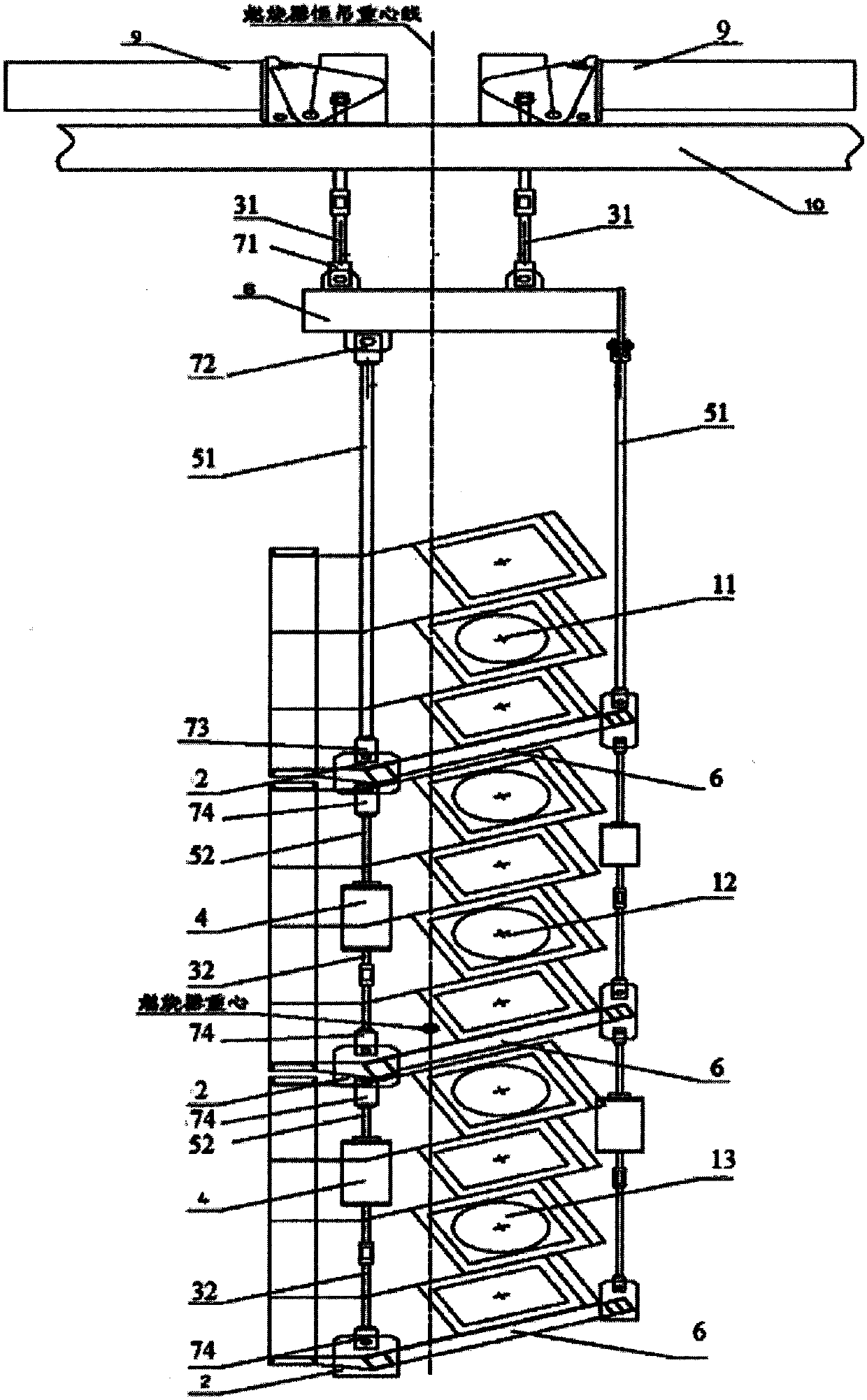
[0043] Such as image 3 Shown is the structural schematic diagram of the double constant spring hanger balance suspension of the three-stage bracket type tilt angle burner in the third embodiment. The double constant force spring hanger balance suspension three-stage hanger type tilt angle burner includes a balance hanging beam 8, two constant force spring hangers 9 and a main burner, the main burner is from top to bottom The first group of inclination burners 11, the second group of inclination burners 12 and the third group of inclination burners 13 are arranged in sequence below, and the minimum distance between adjacent groups of inclination burners is 270mm. The structure of the three groups of inclination burners Slightly different, but all form an angle of 23° with the horizontal.

[0044] A bracket 6 is provided at the bottom of each group of angle burners. The angle between the bracket 6 and the horizontal plane is consistent with the inclination angle of the inclinatio...


PUM


Abstract

The invention provides a device for balanced suspension of dip angle burners with double constant-force spring hangers. The device is characterized in that the device comprises a balanced hanging beam, the two constant-force spring hangers and a main burner; the main burner comprises at least two sets of dip angle burners which are sequentially arranged from top to bottom; a hanging bracket is arranged on the top of each set of dip angle burner, or a carriage is arranged at the bottom of each set of dip angle burner; the two constant-force spring hangers are arranged on a bearing beam; each of the two constant-force spring hangers is connected with the balanced hanging beam through a first connecting rod device, each of the two sides of the balanced hanging beam is connected with the hanging bracket or the carriage of the tip angle burner on the topmost side through a second connecting rod device, and the two sides of the hanging brackets or the carriages of the two adjacent sets of tip angle burners are connected through third connecting rod devices. By the adoption of the device, the entire set of dip angle burners can be reliably suspended, and the device can effectively solve the problem of differential expansion between various sets of dip angle burners.

Description

Technical field [0001] The invention relates to a hanger device, in particular to a burner hanger device for a supercritical boiler in a power station. Background technique [0002] The deformation and expansion of the burner during commissioning directly affect the safe and economic operation of the boiler unit. When the boiler starts in cold and hot states, the shrinkage or expansion deformation caused by the temperature difference between the vertical and horizontal directions of the water wall tube will directly affect the expansion of the burner. At the same time, the end of the burner near the furnace to the fire surface is affected by the high-temperature radiant heat in the furnace, and the temperature is relatively high, while the other end connected to the air and powder pipe is located outside the furnace, and the temperature is relatively low, making the burner itself have a mixing height, Deformation caused by the difference in temperature between width and length. ...

Claims


Application Information

Patent Timeline
Patent Type & Authority Patents(China)
IPC IPC(8): F23C5/02
CPCF23C5/02F23C2700/06
Inventor 李江涛赵鹏龚丽颖
Owner SHANGHAI BOILER WORKS
Learn More