Continuous steam generator

a technology of continuous steam and generator, which is applied in the direction of steam boiler components, steam boilers, furnace tubes, etc., can solve the problem that no further pipes are available as rear wall support pipes, and achieve the effect of ensuring the cooling of the combustion chamber nose, simple technical construction, and high level of operational reliability

Active Publication Date: 2014-10-07
SIEMENS ENERGY GLOBAL GMBH & CO KG
View PDF18 Cites 1 Cited by
  • Summary
  • Abstract
  • Description
  • Claims
  • Application Information

AI Technical Summary

Benefits of technology

[0020]An object of the invention is to specify a continuous steam generator of the above-mentioned type which has a simple design while providing a particularly long service life.
[0024]In an advantageous embodiment, a number of support pipes are downstream on the flow medium side of a further part of the steam generator pipes of the nose at their upper end, which are essentially routed vertically to a cover of the combustion chamber. Support pipes are also thereby available, which connect the nose and lower part of the combustion chamber linked to the nose with the cover, and thus serve to ensure reliable suspension. As flow medium flows through these support pipes, they expand just as the remaining parts of the combustion chamber, and an even expansion of all four combustion chamber walls takes place and no impermissible tensions arise at the connections of the walls.
[0025]In a further advantageous embodiment all the steam generator pipes of the part of the surrounding wall facing the vertical gas flue on the flow medium side steam generator pipes are downstream of the nose. It is thereby ensured that the entire flow medium flows out of the combustion chamber rear wall or its lower steam generator pipes into the nose, and adequate cooling of the nose is thus ensured. As a result of its exposed position in the interior of the combustion chamber, the nose has a particularly high heat input.
[0027]To this end a number of connecting pipes are downstream of the support pipes routed to the lower end of the nose, which lead into pipes downstream of the steam generator pipes of the upper area of the combustion chamber. The media flow branched for the support pipes is thus switched parallel to the further steam generator pipes of the upper area of the combustion chamber and fed into the system once more. Complete usage of the media flows of the support pipes is thus possible.
[0028]The advantages connected with the invention lie in particular in the fact that as a result of the downstream location of a number of support pipes on the flow medium side, which are essentially routed vertically to the lower end of the nose, on at least one part of the steam generator pipes of the nose at their upper end, a particularly simple technical construction coupled at the same time with a high level of operational reliability of the steam generator is possible. On the one hand, steam generator pipes are fully employed for load take-up by the boiler framework, and no separate constructions such as for example constant hangers are used, while on the other hand by means of this construction the entire water-steam flow of the rear wall is available for the nose, and adequate cooling of the combustion chamber nose is ensured. Furthermore, largely similar temperatures obtain in the pipe walls, without a separate and laborious drilling of the nose or a complicated transition with changes in the geometry of the pipes being necessary.

Problems solved by technology

Then, however, no further pipes are available as support pipes for the rear wall.

Method used


Image

  • Continuous steam generator
  • Continuous steam generator

Examples


Embodiment Construction

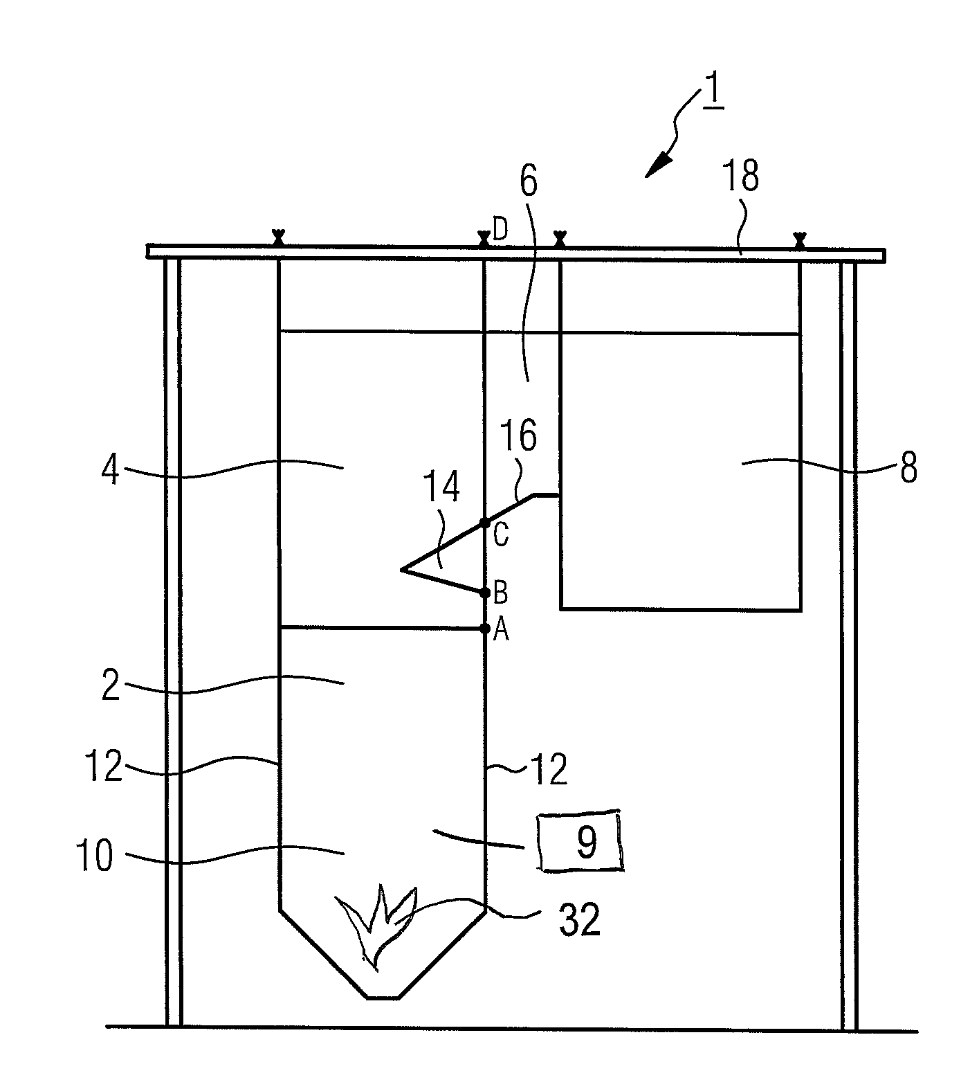
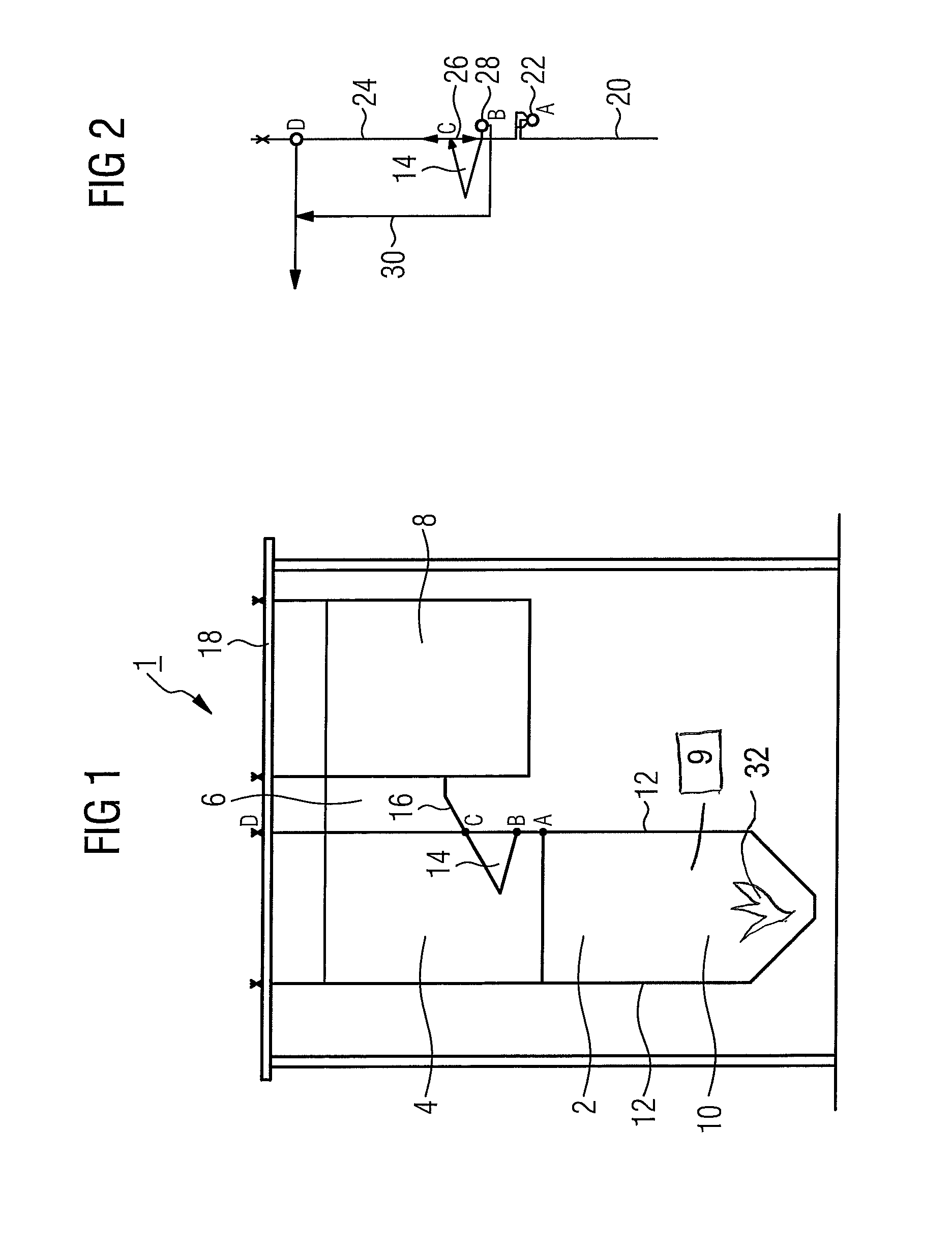
[0033]The continuous steam generator 1 according to FIG. 1 comprises a combustion chamber 2 embodied as a vertical gas flue, which is downstream of a horizontal gas flue 6 in an upper area 4. A further vertical gas flue 8 joins the horizontal gas flue 6.

[0034]In the lower region 10 of the combustion chamber 2 a number of burners 32 (not shown in greater detail) are provided which combust liquid or solid fuel in the combustion chamber. The surrounding wall 12 of the combustion chamber 2 is formed of steam generator pipes welded together in a gas-tight manner into which a flow medium—usually water—is pumped by a pump 9 (not shown in greater detail), said flow medium being heated by the heat produced by the burners. In the lower region 10 of the combustion chamber 2, the steam generator pipes can be oriented either spirally or vertically. In the case of a spiral arrangement, although comparatively greater design complexity is required, the resulting asymmetries between parallel tubes a...


PUM


Abstract

A continuous steam generator with a combustion chamber having a number of burners for fossil fuel and an outside wall composed of steam generator pipes that are welded to each other gas-tight is provided. A vertical gas flue is connected downstream of the combustion chamber on the hot gas side in an upper area via a horizontal gas flue, wherein a part of the outside wall facing the vertical gas flue and below the horizontal gas flue is inclined inward and thus forms a nose projecting into the combustion chamber with the bottom of the adjacent horizontal gas flue. Support pipes are connected downstream of at least one part of the steam generator pipes of the nose at the upper end thereof on the flow medium side, wherein the support pipes are guided substantially vertically to the lower end of the nose.

Description

CROSS REFERENCE TO RELATED APPLICATIONS[0001]This application is the US National Stage of International Application No. PCT / EP2009 / 064205 filed Oct. 28, 2009, and claims the benefit thereof. The International Application claims the benefits of European Patent Application No. 08019643.9 EP filed Nov. 10, 2008. All of the applications are incorporated by reference herein in their entirety.FIELD OF INVENTION[0002]The invention relates to a continuous steam generator comprising a combustion chamber having a number of burners for fossil fuel and an outside wall composed of steam generator pipes that are welded to each other in a gas-tight manner, wherein a vertical gas flue is connected downstream of the combustion chamber on the hot gas side in an upper area through a horizontal gas flue, wherein a part of the outside wall facing the vertical gas flue and below the horizontal gas flue is inclined inward and thus forms a nose projecting into the combustion chamber.BACKGROUND OF INVENTION...

Claims


Application Information

Patent Timeline
Patent Type & Authority Patents(United States)
IPC IPC(8): F22B7/00F22B21/34F22B29/06F22B37/62
CPCF22B21/343F22B29/061F22B37/62F22B21/34F22B29/06
Inventor EFFERT, MARTINSCHNEIDER, ANDREAS
Owner SIEMENS ENERGY GLOBAL GMBH & CO KG
Why Eureka
Try Eureka