
Thumper circuit

A buzzer and circuit technology, applied to instruments, sound-generating devices, etc., can solve problems such as instability

Inactive Publication Date: 2016-05-18
HONG FU JIN PRECISION IND WUHAN CO LTD +1
View PDF7 Cites 0 Cited by
  • Summary
  • Abstract
  • Description
  • Claims
  • Application Information

AI Technical Summary

Problems solved by technology

[0002] The sound of the existing buzzer during use is loud and small and unstable

Method used


Image

  • Thumper circuit
  • Thumper circuit
  • Thumper circuit

Examples


Embodiment Construction

[0013] Below in conjunction with accompanying drawing and preferred embodiment the present invention is described in further detail:

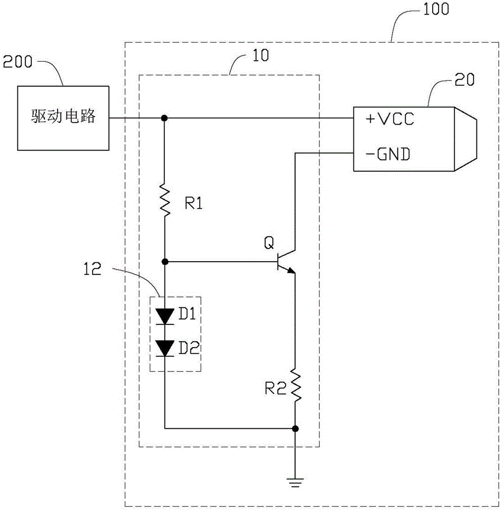
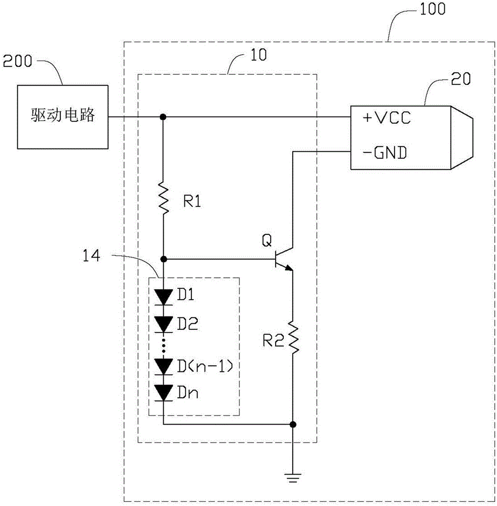
[0014] Please refer to figure 1 , The first preferred embodiment of the buzzer circuit 100 of the present invention is connected to a driving circuit 200 , and the driving circuit 200 is used to drive the buzzer circuit 100 . The buzzer circuit 100 includes a control unit 10 and a buzzer 20 .

[0015] The control unit 10 includes a first resistor R1 , a second resistor R2 , a transistor Q and a constant voltage element 12 . The constant voltage element 12 includes two diodes D1 and D2 connected in series. The buzzer 20 includes a power pin VCC and a ground pin GND. The power supply pin VCC is connected to the driving circuit 200 . The base of the triode Q is connected to the power pin VCC of the buzzer 20 through the first resistor R1. The collector of the transistor Q is connected to the ground pin GND of the buzzer 20 . The emitter of t...


PUM


Abstract

A thumper circuit is connected with a drive circuit and comprises a thumper and a control unit. The control unit comprises an electronic switch, a first resistor, a second resistor and a constant voltage element. A control end of the electronic switch is connected with a power supply pin of the thumper through the first resistor, and is also grounded through the constant voltage element. A first end of the electronic switch is connected with a grounding pin of the thumper. A second end of the electronic switch is grounded through the second resistor. When the thumper receives a high-level driving signal, the electronic switch is closed, and the voltage between the control end and the second end of the electronic switch is constant, so as to cooperate with the constant voltage element to provide a constant voltage for two ends of the second resistor, and the grounding pin of the thumper is grounded successively through the electronic switch and the second resistor. According to the thumper circuit of the present invention, the voltage of the second resistor is constant, so that the current flowing through the thumper is constant, thereby stabilizing the sound of the thumper during operation.

Description

technical field [0001] The invention relates to a buzzer circuit. Background technique [0002] The sound that the existing roarer sends out during use is loud and small at times, and is unstable. Contents of the invention [0003] In view of the above, it is necessary to provide a buzzer circuit to stabilize the sound of the buzzer when it is working. [0004] A buzzer circuit connected to a drive circuit, the buzzer circuit comprising: [0005] A buzzer, including a power pin and a ground pin, the power pin is connected to the driving circuit to receive a driving signal from the driving circuit; and [0006] A control unit, including an electronic switch, a first resistor, a second resistor and a constant voltage element, the control terminal of the electronic switch is connected to the power supply pin of the buzzer through the first resistor, the electronic The control end of the switch is also grounded through the constant voltage element, the first end of the elec...

Claims


Application Information

Patent Timeline
IPC IPC(8): G10K9/12
CPCG10K9/12
Inventor 黄永兆
Owner HONG FU JIN PRECISION IND WUHAN CO LTD
Features
  • Generate Ideas
  • Intellectual Property
  • Life Sciences
  • Materials
  • Tech Scout
  • Unparalleled Data Quality
  • Higher Quality Content
  • 60% Fewer Hallucinations
Learn More