
Identification method of reactive power coupling degree in power system based on branch reactive power flow betweenness

A power system and power flow intermediary technology, applied in the direction of reactive power adjustment/elimination/compensation, reactive power compensation, circuit devices, etc., can solve the problem of not being able to better improve the voltage quality of the power system and the scientific basis for reactive voltage control , unable to effectively identify the strength of reactive power coupling and other issues

Active Publication Date: 2018-06-22
CHONGQING UNIV
View PDF3 Cites 0 Cited by
  • Summary
  • Abstract
  • Description
  • Claims
  • Application Information

AI Technical Summary

Problems solved by technology

The main disadvantages of this method are: ① This method needs to transform the ratio of the reactive power provided by the reactive power source node to other nodes to the reactive power output of the reactive power source node into the distance between nodes through logarithmic transformation to enhance its identification of nodes Capability of reactive coupling degree between
③This method has unreasonable identification results when identifying the reactive power coupling degree between grid nodes
For example, a 10Mvar reactive source node and another 100Mvar reactive power node all deliver 10Mvar reactive power to the same node. According to the method of the document, the reactive power provided by the 10Mvar reactive source to this node accounts for 10% of its reactive power output. The ratio is 1, and the corresponding ratio of 100Mvar reactive power source is 0.1, the former has stronger reactive power coupling than the latter due to the small distance between nodes, which is obviously unreasonable
Therefore, using this method to identify the reactive coupling degree between nodes in the power grid cannot effectively identify the strength of the reactive coupling degree between nodes, and cannot reveal the reactive coupling degree between power system nodes in essence, so it cannot be a reactive coupling degree Power and voltage control provides a reliable scientific basis and cannot better improve the voltage quality of the power system

Method used


Image

  • Identification method of reactive power coupling degree in power system based on branch reactive power flow betweenness
  • Identification method of reactive power coupling degree in power system based on branch reactive power flow betweenness
  • Identification method of reactive power coupling degree in power system based on branch reactive power flow betweenness

Examples


Embodiment

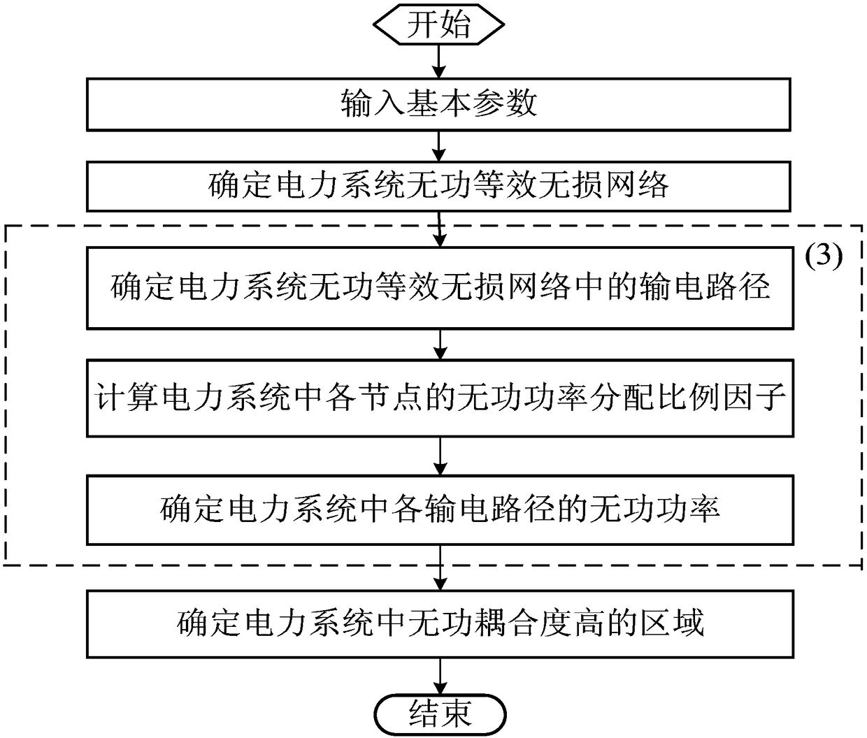
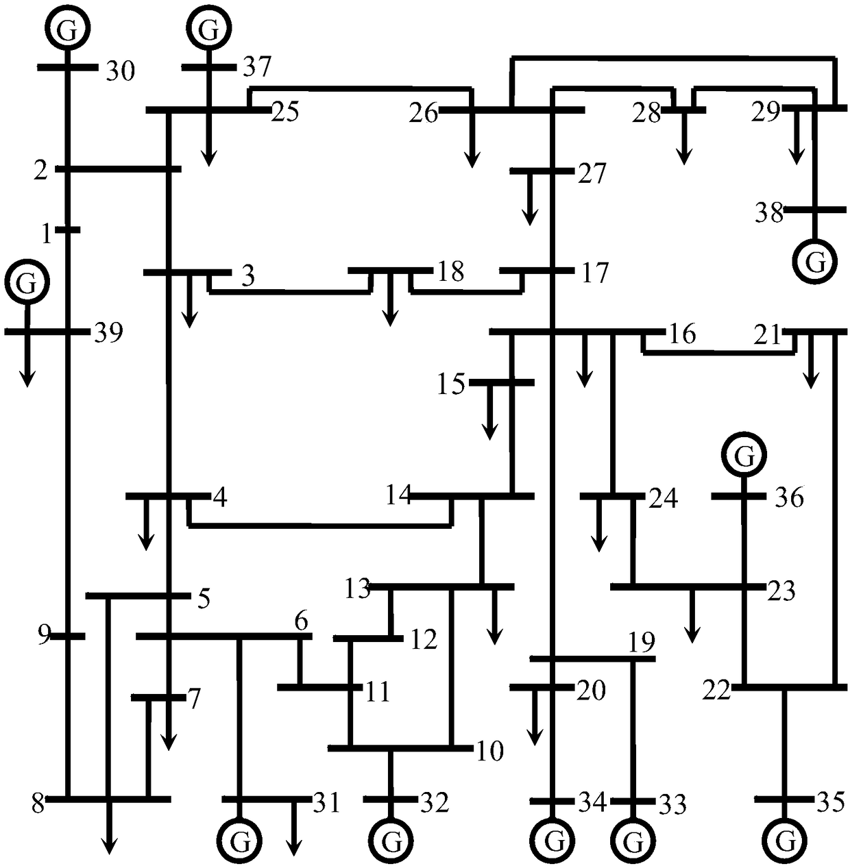
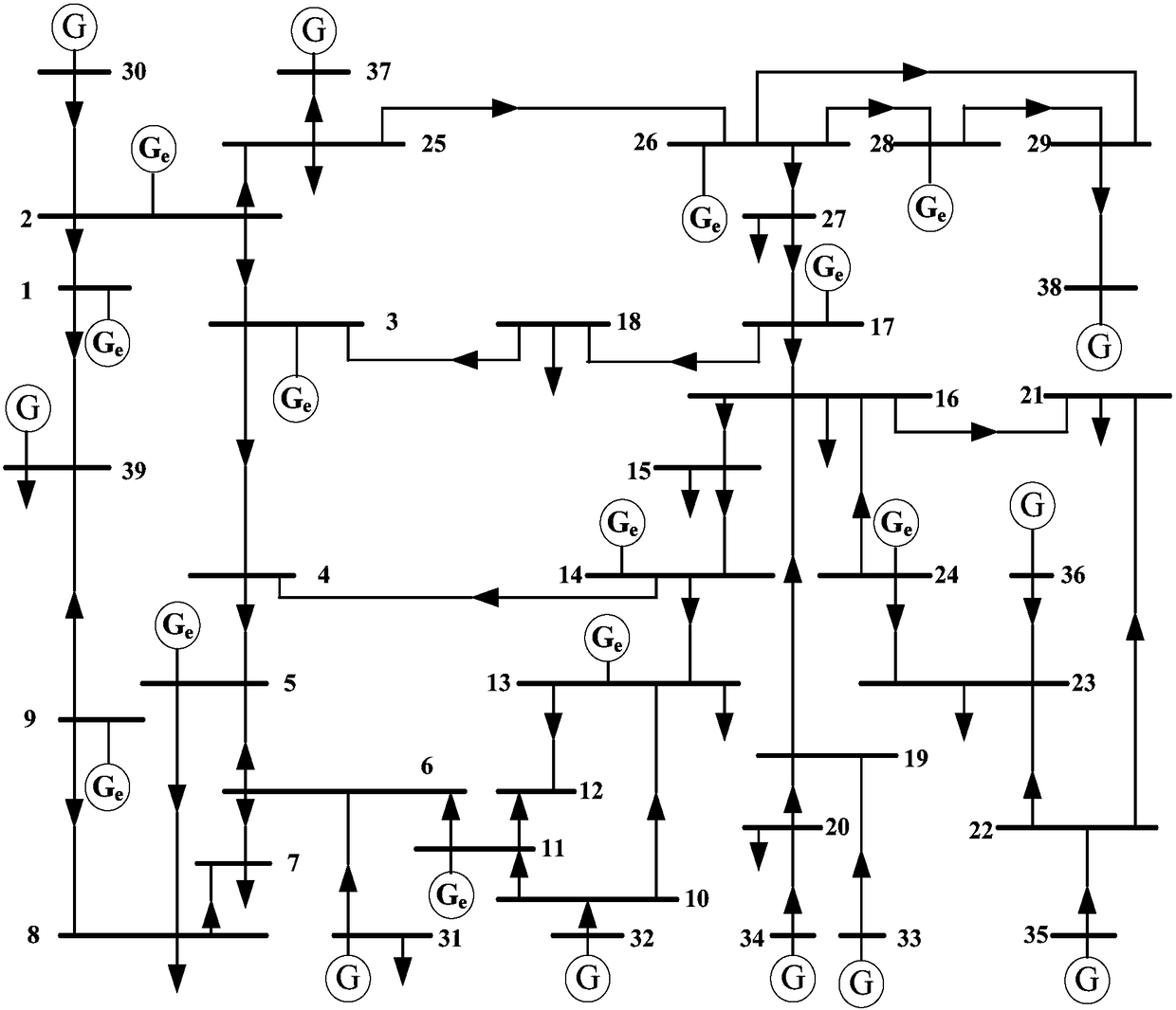
[0066] Such as figure 1 , 2 As shown, the specific steps of a power system reactive coupling degree identification method based on branch reactive power flow betweenness are as follows:

[0067] (1) Input basic parameters

[0068] First enter the basic parameters of the power system. The basic parameters of the power system include node number (1, 2, ..., 39), node type, node corresponding voltage level, active power load of each node (P l ) and reactive power load (Q l ), the number of nodes connected to generators, the active power output by each generator (P g ) and reactive power (Q g ), the node numbers at the beginning and end of each line, line resistance (R), line reactance (X) and line susceptance (B), each transformer node number, transformer ratio (K T ), transformer resistance (R T ) and transformer reactance (X T ), reference voltage (U B =345kV) and reference power (S B =100MVA), scale factor (λ=0.1).

[0069] (2) Determine the reactive power equivalen...


PUM


Abstract

The invention provides an electric power system reactive coupling degree identification method based on a branch reactive power flow betweenness and belongs to the technical field of electric power system automation. The method is characterized in that basic parameters are firstly input by a computer through a program, then an electric power system reactive equivalent lossless network is determined, reactive power of each power transmission path in the electric power system is determined, and finally, the region high in reactive coupling degree in the electric power system is determined. In the electric power system reactive coupling degree identification process, the influences of lines and transformer branches in the system are considered, and the branch reactive power flow betweenness obtained by means of reactive power flow tracking can accurately reflect the effect of each node in the reactive power transmission of the electric power system and can essentially reveal the reactive coupling degree of the electric system, so that the validity and accuracy of electric power system reactive coupling degree identification is improved. The electric power system reactive coupling degree identification method can be widely applied to reactive coupling degree identification of the electric power system, and a scientific basis is provided for reactive voltage control of the electric power system, so that the voltage quality of the electric power system is better improved.

Description

technical field [0001] The invention belongs to the technical field of power system automation, and in particular relates to a reactive power coupling degree identification method of a power system based on branch reactive power flow betweenness. Background technique [0002] Voltage quality is one of the basic technical requirements for power system operation. With the large-scale interconnection of power systems, the problem of reactive power and voltage control is also brought about while improving resource utilization. By monitoring the system node voltage and controlling the reactive power supply, the voltage can be operated within the allowable range, which not only helps to ensure the voltage quality of the system operation, but also improves the safety of the system operation. In the process of reactive power and voltage control, the degree of reactive power coupling in the power system has a great influence on the effect of reactive power and voltage control. Reac...

Claims


Application Information

Patent Timeline
Patent Type & Authority Patents(China)
IPC IPC(8): H02J3/18
CPCH02J3/18H02J2203/20Y02E40/30
Inventor 王韶黄晗尹洪涛张文龙邓先芳汪俊宇张成瑜黄驰
Owner CHONGQING UNIV
Learn More