Oil supply device for engine

一种供应装置、发动机的技术,应用在发动机的润滑、发动机元件、机器/发动机等方向,能够解决驱动损耗等问题

Active Publication Date: 2016-05-18
MAZDA MOTOR CORP
View PDF3 Cites 8 Cited by
  • Summary
  • Abstract
  • Description
  • Claims
  • Application Information

AI Technical Summary

Problems solved by technology

[0004] However, while the required amount of oil (required hydraulic pressure) varies depending on the operating state of the engine, if only the flow control valve is controlled, even if the required oil amount (required hydraulic pressure) is met, there will be a lot of damage to the overall oil pump. A situation where drive loss occurs due to useless work
Therefore, there is still room for improvement in this regard

Method used


Image

  • Oil supply device for engine
  • Oil supply device for engine
  • Oil supply device for engine

Examples


Embodiment Construction

[0024] Hereinafter, a preferred embodiment of the present invention will be described in detail with reference to the drawings.

[0025]

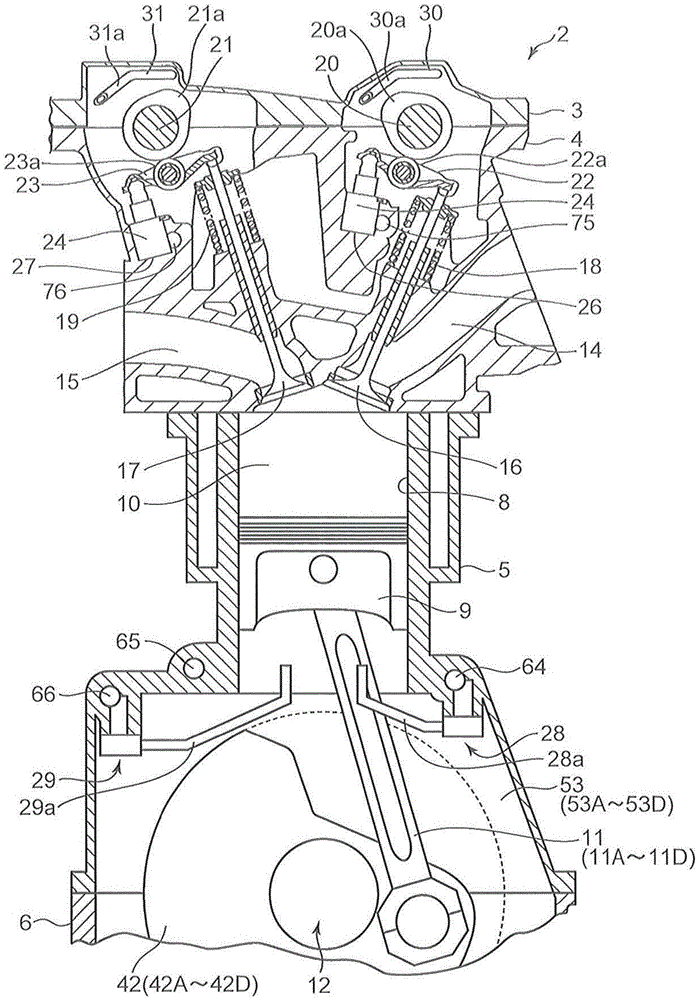
[0026] figure 1 A multi-cylinder engine 2 (hereinafter simply referred to as engine 2 ) to which the oil supply device according to the present invention is applied is shown. The engine 2 is the first cylinder #1 to the fourth cylinder #4 along with figure 1 In-line four-cylinder gasoline engines arranged in series in a direction perpendicular to the plane of the paper are mounted on vehicles such as automobiles.

[0027] The engine 2 includes a camshaft cover 3 connected up and down, a cylinder head 4, a cylinder block 5, a crankcase 6 and an oil pan 7 (refer to Image 6 ). Four cylinder holes 8 are formed in the cylinder block 5, and a piston 9 is slidably accommodated in each cylinder hole 8, and a combustion chamber 10 is formed in each cylinder by the piston 9, the cylinder hole 8, and the cylinder head 4. . In addition, each pi...


PUM


Abstract

Provided is an oil supply device comprising: an oil pump; a main oil supply path into which oil discharged from the oil pump is introduced; an auxiliary oil supply path that is connected to the downstream side of the main oil supply path; a first oil supply section that is connected to the main oil supply path and that supplies oil to the crankshaft bearing section of a specific crank journal among a plurality of crank journals; a second oil supply section that is connected to the auxiliary oil passage and that supplies oil to a crankshaft bearing section other than that of the specific crank journal; a plurality of hydraulic operation sections that include at least a first oil supply path and a second oil supply path; a hydraulic pressure sensor that detects the hydraulic pressure of the main oil supply path; and a control device that, among required hydraulic pressures that are the hydraulic pressures of the plurality of hydraulic operation sections and that correspond to the operation state of an engine, sets the largest required hydraulic pressure as a target hydraulic pressure and controls the discharge rate of the oil pump so that the hydraulic pressure detected by the hydraulic pressure sensor becomes the target hydraulic pressure.

Description

technical field [0001] The present invention relates to an engine oil supply device for supplying engine oil to various parts of the engine of an automobile or the like. Background technique [0002] For example, Patent Document 1 discloses an oil supply device that introduces oil from a specific crank journal of the crankshaft into the inside of the crankshaft, and supplies the oil to each crankpin through an internal passage formed in the crankshaft. This oil supply device supplies the oil discharged from the oil pump through the main oil passage to the crankshaft bearing part (referred to as the specific bearing part) that supports the above-mentioned specific crankshaft journal, and on the other hand, through the branch oil passage branched from the main oil passage, The engine oil is supplied to the crankshaft bearing portion that supports the crankshaft journals other than the above-mentioned specific crankshaft journals. In addition, the oil supply is controlled by a...

Claims


Application Information

Patent Timeline
Patent Type & Authority Applications(China)
IPC IPC(8): F01M1/16F01M1/06F01M1/08F01M9/10
CPCF01M1/16F01L1/3442F01L2001/34423F01L2810/02F01M1/02F01M1/06F01M1/08F01M9/10F01M2001/062F01M2011/023F16N2280/00
Inventor 上村圭一松浦弘和小口智弘本田绚大
Owner MAZDA MOTOR CORP
Why Eureka
Try Eureka