Pressure pipeline leaking stoppage device

A technology for pressure pipes and pipes, applied in pipe elements, pipes/pipe joints/fittings, mechanical equipment, etc., can solve the problems of poor pipe sealing, inconvenient use of devices, easy leakage of pipes, etc., and achieve good sealing performance, The effect of convenient operation and easy operation of the device

Inactive Publication Date: 2021-04-16
烟台市特种设备检验研究院
View PDF7 Cites 3 Cited by
  • Summary
  • Abstract
  • Description
  • Claims
  • Application Information

AI Technical Summary

Problems solved by technology

[0003] When the pressure pipeline plugging device in the prior art is used, the sealing performance of the pipeline is poor, and the pipeline is easy to leak. At the same time, the device is not easy to use and the operation is complicated.

Method used


Image

  • Pressure pipeline leaking stoppage device
  • Pressure pipeline leaking stoppage device
  • Pressure pipeline leaking stoppage device

Examples


Embodiment

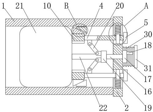
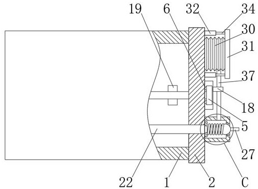
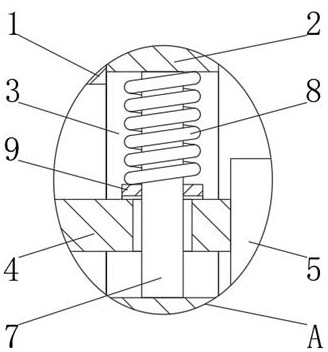
[0027] A pressure pipe leak plugging device, comprising a pipe 1, one end of the pipe 1 is contacted with a support plate 2, and a chute 3 is opened in the support plate 2, and there are two chute 3, and the two The chute 3 is symmetrically distributed in the support plate 2, the chute 3 is slidably connected with a support rod 4, one end of the support rod 4 is welded with a stopper 5, and a guide rod 7 is arranged in the chute 3, so The guide rod 7 is welded on the support plate 2, the first spring 8 is arranged on the outside of the guide rod 7, the outer side of the guide rod 7 is slidingly sleeved with a backing plate 9, and the outer side of the guide rod 7 is slidingly sleeved There is a support rod 4 , the backing plate 9 is in contact with the support bar 4 , one end of the first spring 8 is bonded to the support plate 2 , and the other end is bonded to the backing plate 9 .

[0028] Wherein, a bump 6 is welded on the stopper 5 , and the outer side of the bump 6 is co...


PUM


Abstract

The invention discloses a pressure pipeline leaking stoppage device . The pressure pipeline leaking stoppage device comprises a pipeline, wherein one end of the pipeline is in contact connection with a supporting plate, sliding grooves are formed in the supporting plate, the number of the sliding grooves is two, the two sliding grooves are symmetrically distributed in the supporting plate, a supporting rod is in sliding connection in each sliding groove, and a check block is welded to one end of each supporting rod; a guide rod is arranged in each sliding groove, the guide rods are welded to the supporting plate, a first spring is arranged at the outer side of each guide rod, the outer side of each guide rod is sleeved with a base plate in a sliding manner, the outer side of each guide rod is sleeved with a supporting rod in a sliding manner, each base plate is in contact connection with the corresponding supporting rod, and one ends of the first springs are bonded to the supporting plate; and the other ends of the first springs are adhered to the base plates. The invention relates to the pressure pipeline leaking stoppage device. The pressure pipeline leaking stoppage device has the characteristics of being convenient to operate and good in sealing performance.

Description

technical field [0001] The invention belongs to the technical field of pipeline plugging, in particular to a pressure pipeline leakage plugging device. Background technique [0002] In modern production, there are various pipelines for water, oil, and gas transmission, and there are water pipes, gas pipes, and heating pipes in living facilities. Due to ground subsidence, external force impact, and man-made damage, the pipeline ruptures, especially the cracking of the weld seam, causing oil, gas, and water leakage. It must be repaired in time, otherwise it will not only cause waste of resources, affect production and life, but also cause environmental pollution. . Because there is no special-purpose pipeline plugging device, the general repair method is to cut off the water or gas first, stop the normal operation of the fluid in the pipeline, and then replace with new pipe fittings or weld repairs or block with other materials. The above method must be maintained by profess...

Claims


Application Information

Patent Timeline
Patent Type & Authority Applications(China)
IPC IPC(8): F16L55/134
Inventor 刘曙光
Owner 烟台市特种设备检验研究院
Why Eureka
Try Eureka