Waste collecting container for vacuum cleaner

A technology for garbage collection and collection container, which is applied in the directions of vacuum cleaners, suction filters, cleaning equipment, etc., and can solve the problems of complicated maneuverability of garbage collection bags.

Inactive Publication Date: 2002-10-02
SEB SA
View PDF4 Cites 3 Cited by
  • Summary
  • Abstract
  • Description
  • Claims
  • Application Information

AI Technical Summary

Problems solved by technology

[0013] One of the objects of the present invention is to solve the problems of manoeuvrability and complexity of the garbage collection b

Method used


Image

  • Waste collecting container for vacuum cleaner
  • Waste collecting container for vacuum cleaner
  • Waste collecting container for vacuum cleaner

Examples


Embodiment Construction

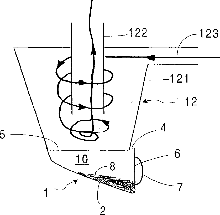
[0046] figure 1 A cyclonic waste separation device 12 is shown, which comprises a frustoconical housing 121 and a pressure delivery pipe 122 . The air drawn in flows through the channel 123 , first spirally descending along the frusto-conical wall 121 , and then ascending along the central axis of the pressure delivery pipe 122 .

[0047] The rubbish 8 separated by the cyclone is collected in a container 1 positioned at the bottom of the device, and the rubbish falls into the collection container under the action of gravity and inertia. The air is discharged free of fine dust particles and is treated further downstream if required.

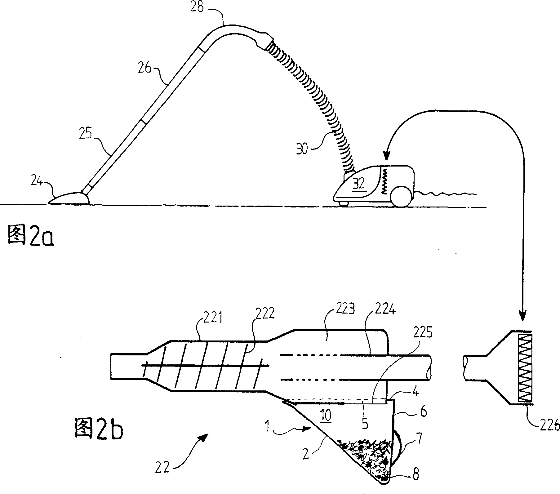
[0048] According to the invention, the collection container 1 comprises a bottom wall 2 for collecting waste, a connecting wall 4 with a cover 5, a wall 6 with a handle 7, and two side walls, not shown, which define a waste Storage room 10. The openings in the connecting wall 4 allow the waste to enter the collection container from the separati...


PUM


Abstract

The invention relates to a disassembled collection container (44) for the collection of waste separated by a cyclone or inertial device of a dust collector of the vacuum cleaner type, said collection container having a plurality of walls (45a, 45b, 46, 48 ), these walls define a storage chamber (54), of which one wall (46) forms the bottom of the collection container (44), called the bottom wall, and at least one wall is equipped with an opening (49), called The connection wall is characterized in that the bottom wall (46) and the connection wall (48) are adjacent, one wall and/or the other wall has a curvature, or there is an inclination between the walls, the connection wall (48) The opening (49) abuts the adjoining area between this wall and said bottom wall (46). According to the present invention, when the collection container (44) is arranged in the dust suction system, it is ventilated and connected to the garbage separation device through the opening (49) of the connecting wall (48).

Description

technical field [0001] The present invention relates to a refuse collection device provided with a vacuum cleaner having an inertial or cyclone refuse separation system. Background technique [0002] This device and its advantages are known: on the one hand, there is no need for filter bags for collecting waste, which are often replaced and thus need to be purchased continuously, and on the other hand, the suction state is more stable and therefore more efficient. It is beneficial to prolong the service life of the motor and improve the dust removal effect. [0003] Such devices generally include a body with an inner tube. The air enters the fuselage tangentially, circulates along a spiral channel that descends around the tube, and throws solid dust particles to the inner surface of the wall. These dust particles are then collected by gravity along the wall into a lower collection container . At the end of the spiral descent, the air, freed of solid dust particles, return...

Claims


Application Information

Patent Timeline
IPC IPC(8): A47L9/10A47L9/16
CPCA47L9/1608A47L9/1658A47L9/1683A47L9/1691
Inventor 罗朗·迪博斯吉勒·迪亚斯科恩
Owner SEB SA
Why Eureka
Try Eureka