Compressor with variable compressor inlet

A technology for compressors and compressor housings, applied in the direction of machines/engines, mechanical equipment, non-variable pumps, etc.

Inactive Publication Date: 2016-05-18
CONTINENTAL AUTOMOTIVE GMBH
View PDF8 Cites 6 Cited by
  • Summary
  • Abstract
  • Description
  • Claims
  • Application Information

AI Technical Summary

Problems solved by technology

Here, the key would be that there is not enough mounting space available for this device and there are robustness issues with regard to cycle times and temperature loads

Method used


Image

  • Compressor with variable compressor inlet

Examples


Embodiment Construction

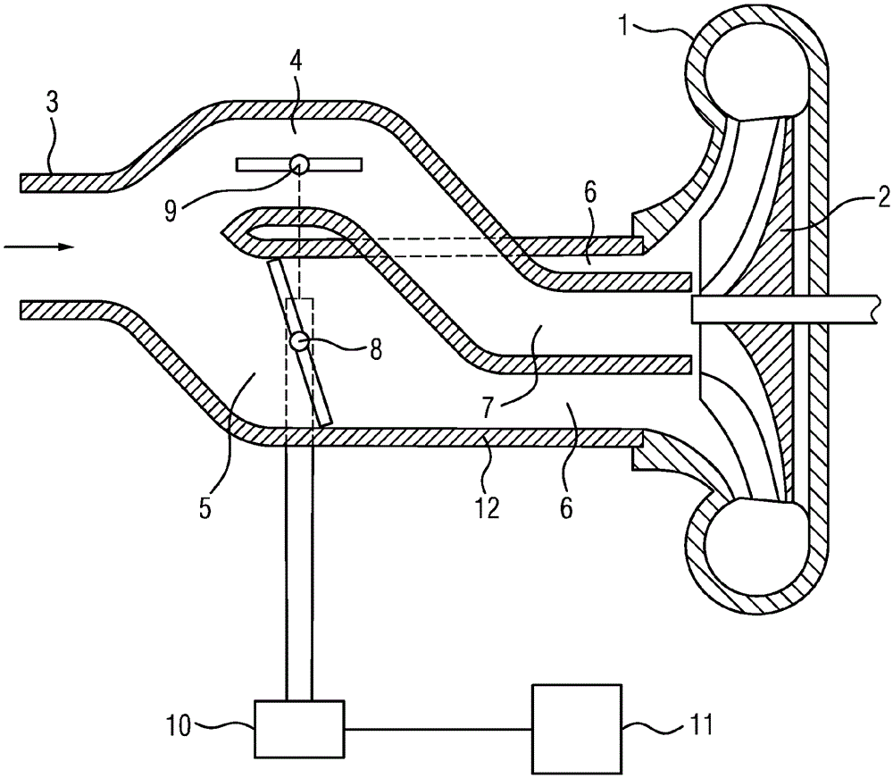
[0020] In the corresponding schematic sectional illustration, the compressor housing 1 with the associated compressor inlet 12 is shown. A compressor wheel 2 with corresponding compressor blades (indicated only schematically) is located in the compressor housing 1 . Air flows from an air intake filter (not shown) into header 3 and from there into compressor inlet 12 . Adjacent to the header 3, the compressor inlet 12 has two separate tubes 4, 5 arranged adjacent to each other into which the header 3 merges. The upper tube 4 shown in the figure extends into the lower tube 5 and thus forms two concentric tubes (ie inner tube 7 and outer tube 6 ) and is adjacent to the compressor housing 1 in the region of the compressor inlet 12 . In this case, the inner tube 7 is directed towards the radially inner region and the outer tube 6 is directed towards the radially outer region of the compressor blade. In terms of cross section, the inner tube 7 has a circular air passage section, w...


PUM


Abstract

A compressor of a turbocharger is described and comprises a compressor housing, a compressor wheel with compressor blades which is mounted therein, and a compressor inlet. The compressor inlet comprises, at least in a section adjacent to the compressor housing, an inner pipe and an outer pipe surrounding the inner pipe. The inner pipe is directed toward the radially inner region of the compressor blades and the outer pipe is directed toward the radially outer region of the compressor blades. The passage cross-section of the outer pipe and / or of the inner pipe can be at least partially blocked, so that the compressor blades can be exposed to a variable flow. The approach flow to the compressor wheel is therefore optimized as a function of the engine load.

Description

technical field [0001] The invention relates to a compressor for a turbocharger, in particular an exhaust-gas turbocharger, having the features stated in the preamble of patent claim 1 . Background technique [0002] Due to the optimization of spark-ignition engines with the aim of reducing consumption, the requirements placed on the operating range of turbochargers are increasing day by day. The most important reason for this is that when the engine is under partial load, the engine runs at the lowest possible speed but with high torque to increase efficiency. For this purpose, high boost pressures and relatively low volume flows are required. Therefore, the approach flow to the compressor wheel has to be optimized for a wide volumetric flow range. The need to meet higher future requirements makes it necessary to implement a switchable approach flow so that a larger or smaller flow cross section can be selected depending on the volume flow. It is thus possible to achieve...

Claims


Application Information

Patent Timeline
Patent Type & Authority Applications(China)
IPC IPC(8): F04D27/02F04D29/42
CPCF04D27/0253F04D29/4213F05D2250/51F05D2220/40F02D41/0007F04D27/003F04D29/4206
Inventor M.魏格尔P.格拉斯
Owner CONTINENTAL AUTOMOTIVE GMBH
Why Eureka
Try Eureka