Denitration reductant adding control method based on time difference matching and control device of control method

A control method and reducing agent technology, applied in the direction of separation methods, chemical instruments and methods, gas treatment, etc., can solve the problem that the change of reducing agent addition cannot be matched and controlled in time, and achieve the effects of reducing adverse effects, easy implementation, and simple operation

Active Publication Date: 2016-05-25
STATE GRID HEBEI ENERGY TECH SERVICE CO LTD
View PDF13 Cites 19 Cited by
  • Summary
  • Abstract
  • Description
  • Claims
  • Application Information

AI Technical Summary

Problems solved by technology

[0004] In order to solve the problem that the concentration of pollutants or flue gas fluctuates greatly and violently, as well as changes in conventional lifting loads, the addition of reducing agent and its change cannot be matched and controlled in time, and at the same time realize the molar ratio of reducing agent ammonia and nitrogen oxides Control, reducing the large delay and thick line control in the conventional control method, the present invention provides a denitrification reducing agent addition control method and its control device based on time difference matching

Method used


Image

  • Denitration reductant adding control method based on time difference matching and control device of control method
  • Denitration reductant adding control method based on time difference matching and control device of control method
  • Denitration reductant adding control method based on time difference matching and control device of control method

Examples


Embodiment Construction

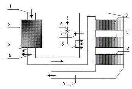
[0025] Such as figure 1 As shown, a control device based on a time difference matching denitrification reducing agent addition control method includes a flue gas pipeline 1, an economizer heat exchange device 2 and a catalyst layer 8, and the economizer heat exchange device 2 and catalyst layer 8 The flue gas pipeline 1 is sequentially divided into an intake flue gas pipeline 1-1, a denitrification flue gas pipeline 1-2, and an outlet flue gas pipeline 1-3. Flue gas analysis test point A3, flue gas velocity and flow rate test point 4, ammonia injection grid 5 and in-situ online flue gas analysis test point B7, the ammonia injection grid 5 is connected to the regulating valve 6 for controlling the amount of ammonia added , The online flue gas analysis test point D9 is set on the outlet flue gas pipeline 1-3.

[0026] (1) The hot flue gas discharged from the boiler furnace or the hot flue gas is cooled by the economizer heat exchange device 2, and an in-situ online flue gas ana...


PUM


Abstract

The invention relates to a denitration reductant adding control method based on time difference matching and a control device of the control method. By setting in-situ real-time test points, measuring corresponding parameters and depending on actual characteristics of a catalytic deoxidizing reaction of a denitration device, the time difference of flue gas from a flue gas flow speed and flow rate test point to an ammonia spraying region when the flue gas amount and the concentration of pollutants are changed, and the time difference between ammonia/air for spraying into a grating are mainly calculated, so that synchronous non-time-difference mixing is achieved; meanwhile, the flow speed of front nitric oxide and the flow speed of flue gas are taken as feedforward parameters, the concentration of sprayed and mixed nitric oxide and ammonia is taken as the feedback variable, the weight ratio of the feedforward to the feedback is reasonably set and adjusted, the reductant and the nitric oxide after mixed in flue gas react based on set efficiency before entering the denitration device, the amount of ammonia/nitrogen is rapidly and timely adjusted and matched and flexibly controlled under the working conditions such as various change amplitudes and wild fluctuations, the problem of adverse effects caused by the denitration device, a unit and the like is solved, and a significant effect of promoting pollution reduction is achieved.

Description

technical field [0001] The invention relates to the technical field of reducing agent addition control in the technical field of selective catalytic reduction and denitrification in thermal power unit or boiler flue gas, in particular to a denitrification reducing agent addition control method based on time difference matching and a control device thereof. Background technique [0002] Flue gas denitrification by selective catalytic reduction method is the most widely used denitrification technology in thermal power units and cement and steel industries. It has a series of advantages such as high denitrification efficiency and small secondary pollution, so it is widely used at home and abroad. However, with the increasingly higher requirements of environmental protection standards and the stricter environmental requirements of the public, higher requirements are put forward for the original flue gas denitrification system. [0003] The high-temperature flue gas in the flue g...

Claims


Application Information

Patent Timeline
Patent Type & Authority Applications(China)
IPC IPC(8): B01D53/90B01D53/56
CPCB01D53/56B01D53/90B01D2251/2062B01D2258/0283B01D2259/122
Inventor 宋国升陈崇明候海萍李振海韩忠阁郁金星车凯焦阳
Owner STATE GRID HEBEI ENERGY TECH SERVICE CO LTD
Why Eureka
Try Eureka