
Medicine dispensing device for flower planting

A technology for dispensing devices and flowers, which is applied in the directions of transportation and packaging, mixer accessories, and dissolving, can solve the problems of small production volume of medicinal liquid, undesired appearance, and slow dispensing speed, and achieves high production volume and dispensing speed in the pharmaceutical industry. Fast, quality-assured results

Inactive Publication Date: 2016-05-25
WUPING HONGXIN IND TECH DEV
View PDF7 Cites 1 Cited by
  • Summary
  • Abstract
  • Description
  • Claims
  • Application Information

AI Technical Summary

Problems solved by technology

Pollutants in the office can be inhaled into the plant through the micropores on the back of the leaves of ornamental plants, and the symbiotic microorganisms in the roots of flowers can also automatically decompose pollutants and be absorbed by the roots, but it is the last thing you want to see in the process of planting flowers. In the event of pests and diseases, but plants are living things, they can get sick and infected, so most of them often spray flowers on flowers, and the quality of the liquid medicine is more important in the spraying process. However, the current configuration of the liquid medicine is manually supplied. For proportioning, the dispenser uses a spoon to scoop the raw materials into the mixing bucket according to the ratio of the raw materials for dispensing. This method of dispensing is time-consuming and laborious, the operation is complicated, and dispensing for a long time will cause physical fatigue and easily cause physical damage. Dispensing The speed is slow and the production volume of liquid medicine is small

Method used


Image

  • Medicine dispensing device for flower planting

Examples


Embodiment Construction

[0017] The following will clearly and completely describe the technical solutions in the embodiments of the present invention with reference to the accompanying drawings in the embodiments of the present invention. Obviously, the described embodiments are only some, not all, embodiments of the present invention. Based on the embodiments of the present invention, all other embodiments obtained by persons of ordinary skill in the art without making creative efforts belong to the protection scope of the present invention.

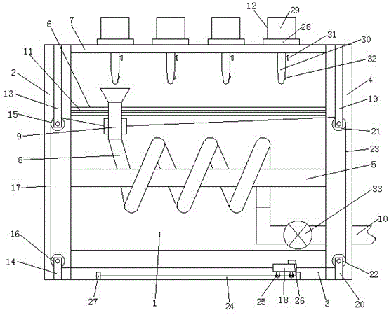
[0018] see figure 1 , the present invention provides a technical solution: a dispensing device for planting flowers, comprising a liquid mixing chamber 1, a first transmission chamber 2, a driving chamber 3 and a second transmission chamber 4, and the liquid mixing chamber 1 is located between the first transmission chamber 2 and the second transmission chamber 4. Between the second transmission chamber 4, and the first transmission chamber 1 is located on the...


PUM


Abstract

The invention discloses a medicine dispensing device for flower planting. The medicine dispensing device comprises a liquid dispensing chamber, a first transmission chamber, a driving chamber and a second transmission chamber. The liquid dispensing chamber is located between the first transmission chamber and the second transmission chamber, and the first transmission chamber is located on the left side of the second transmission chamber. The driving chamber is located at the bottom of the liquid dispensing chamber. A transverse bar, a sliding bar and a bearing bar are arranged inside the liquid dispensing chamber. The sliding bar is located between the transverse bar and the bearing bar. The transverse bar is located at the bottom of the sliding bar. A conveying pipe is arranged on the surface of the transverse bar. One end of the conveying pipe is communicated with a medicine receiver. The other end of the conveying pipe is communicated with one end of a liquid draining pipe. According to the medicine dispensing device for flower planting, manual receiving is not needed, the phenomenon that body injuries are caused when a pharmaceutist works for a long time is avoided, time and labor are saved, operation is easy, the medicine dispensing speed is high, the pharmaceutical production yield is high, and people can conveniently use the medicine dispensing device.

Description

technical field [0001] The invention relates to the technical field of flower planting, in particular to a medicine dispensing device for flower planting. Background technique [0002] With the popularization of office automation, the application of equipment such as printers and copiers, plus carpets, wallpapers, adhesives, etc., pollute the indoor air to varying degrees. To effectively control office pollution, in addition to strengthening ventilation, the simplest and most effective way is to place potted flowers, because green plants are the "swallowers" of harmful substances in the office. Pollutants in the office can be inhaled into the plant through the micropores on the back of the leaves of ornamental plants, and the symbiotic microorganisms in the roots of flowers can also automatically decompose pollutants and be absorbed by the roots, but it is the last thing you want to see in the process of planting flowers. In the event of pests and diseases, but plants are l...

Claims


Application Information

Patent Timeline
IPC IPC(8): B01F15/02
CPCB01F35/716B01F2101/04
Inventor 杨志恒
Owner WUPING HONGXIN IND TECH DEV
Learn More