

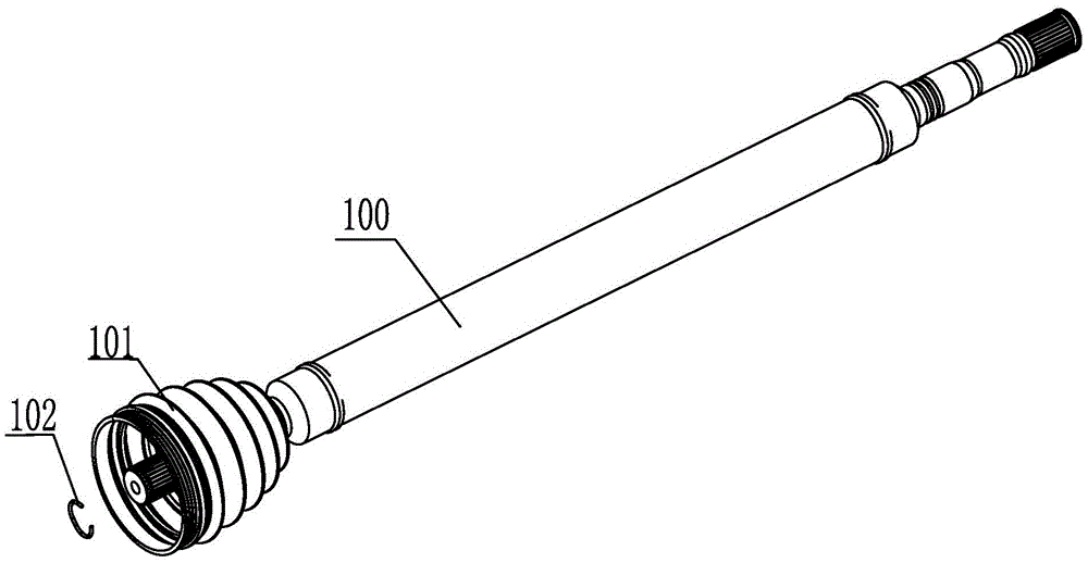
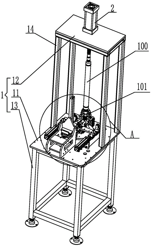
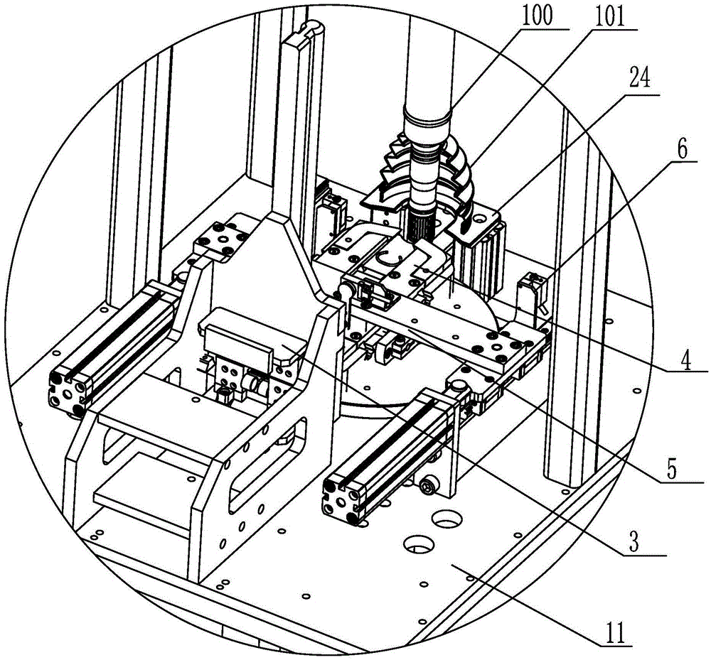
Equipment for automatically assembling C-shaped fastening ring on hollow shaft with sheath
An automatic assembly and clamping ring technology, which is applied in metal processing equipment, metal processing, manufacturing tools, etc., can solve problems such as finger discomfort, C-shaped clamping ring 102 deformation failure, manual operation strength is difficult to grasp, etc., to achieve Guarantee the quality of assembly, reduce the labor intensity of workers, and make the intensity of installation easy to control
- Summary
- Abstract
- Description
- Claims
- Application Information
AI Technical Summary
Problems solved by technology
Method used
Image

Examples
Embodiment Construction
[0044] The implementation of the present invention will be illustrated by specific specific examples below, and those skilled in the art can easily understand other advantages and effects of the present invention from the contents disclosed in this specification.
[0045] It should be noted that the structures, proportions, sizes, etc. shown in the drawings attached to this specification are only used to match the content disclosed in the specification, for those who are familiar with this technology to understand and read, and are not used to limit the implementation of the present invention. Limiting conditions, so there is no technical substantive meaning, any modification of structure, change of proportional relationship or adjustment of size, without affecting the effect and purpose of the present invention, should still fall within the scope of the present invention. within the scope covered by the disclosed technical content. At the same time, terms such as "upper", "lo...
PUM
 Abstract
Description
Claims
Application Information