New energy automobile charger

A new energy vehicle and charging device technology, applied in electric vehicle charging technology, charging stations, electric vehicles, etc., can solve the problems of difficult adaptation of the linkage mechanism and difficult bending of the mechanical arm, and achieve a high degree of automation and a large bending range. Effect

Active Publication Date: 2016-05-25
夏林嘉 +1
View PDF7 Cites 22 Cited by
  • Summary
  • Abstract
  • Description
  • Claims
  • Application Information

AI Technical Summary

Problems solved by technology

However, the biggest problem with the above-mentioned mechanical arm is that it is difficult for the mechanical arm itself to bend at any angle. Although a certain bending function can be achieved through the linkage mech

Method used


Image

  • New energy automobile charger
  • New energy automobile charger
  • New energy automobile charger

Examples


Example Embodiment

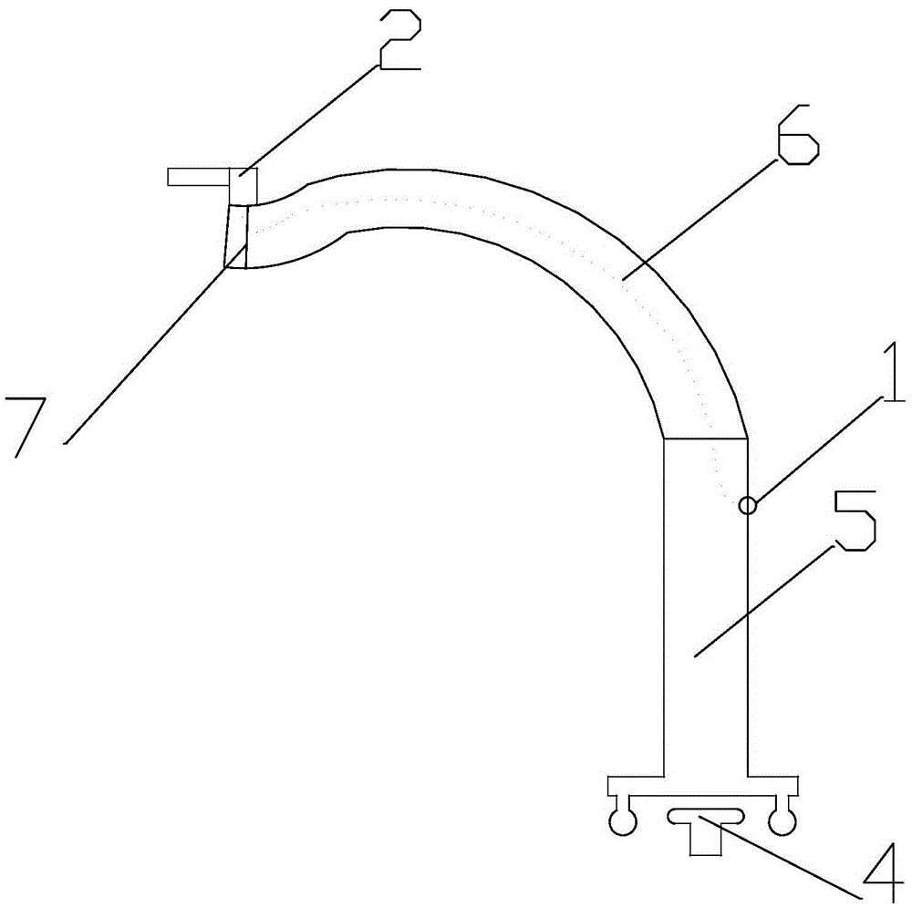
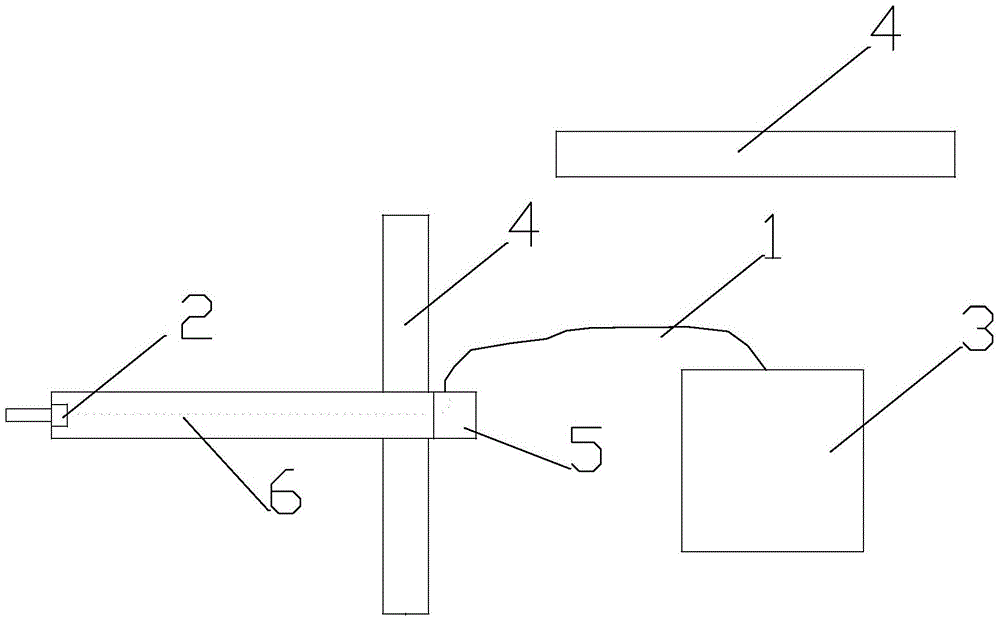
[0015] Embodiment: The present invention includes a charging pile 3 and a charging gun 2 connected to the charging pile 3 through a charging cable 1, and also includes a mechanical arm 6, a guide rail 4 matched with the charging pile 3, and a walking trolley 5 on the guide rail 4. One end of the robotic arm 6 is installed on the trolley 5, and the charging gun 2 is installed on the other end of the robotic arm 6. The guide rail 4 is arranged in parallel on one side of the charging pile 3 or vertically arranged on the side of the charging pile 3. The robot arm 6 is provided with an image recognition sensor 7 for recognizing the socket of a new energy vehicle and a charging gun, wherein the charging cable 1 can be installed on the walking trolley 5 through a crawler.

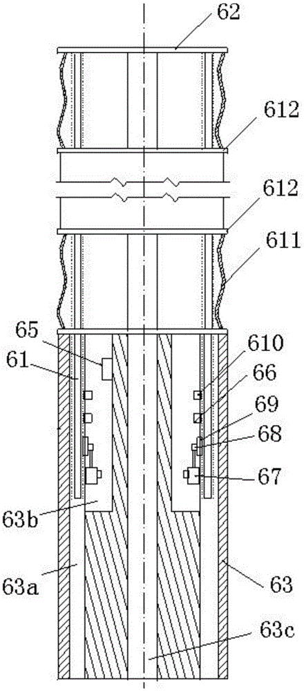
[0016] The mechanical arm 6 includes a screw rod 61 and at least one condyle. The screw rod 61 has at least three. The condyle includes a head module 62 and a base 63 with a guide hole 63a and a mounting cavity 63b. ...


PUM


Abstract

The invention provides a new energy automobile charger, comprising a charge pile and a charge gun connected with the charge pile through a charge wire and also comprising a mechanical arm, a guide rail fitting the charge pile and a travel cart located on the guide rail. One end of the mechanical arm is disposed on the travel cart, and the charge gun is disposed at the other end of the mechanical arm. Wherever a new energy automobile comes, the travel cart can be slid quickly to the new energy automobile, the charge gun is aligned with a charge interface of the automobile through the mechanical arm for charging, the automation level is very high, the mechanical arm may be bent at any angle to form three-dimensional space curvilinearly bent, and sufficient and wide bending range may be provided to the mechanical arm.

Description

technical field [0001] The invention relates to the field of new energy vehicle charging, in particular to a new energy vehicle charging device. Background technique [0002] When the existing new energy vehicles need to be charged, the new energy vehicles are generally driven to the charging pile, and then the new energy vehicles are charged with the charging gun, but this method is too low in automation. Although the field of application of robotic arms is very wide, it is relatively rare to apply robotic arms to new energy vehicle charging devices. That is because common robotic arms include the following methods: The first is to use X / Y / Z three-dimensional Axis running mechanism, that is, the robot arm is installed on a platform with X / Y / Z three-axis superposition operation, and the robot arm is driven to operate in three-dimensional space through the operation of the platform in the X / Y / Z direction. The second type is to add a rotating mechanism on the basis of the abo...

Claims


Application Information

Patent Timeline
IPC IPC(8): B25J5/02B25J18/06B60L11/18
CPCB25J5/02B25J18/06B60L53/16Y02T10/70Y02T10/7072Y02T90/14
Inventor 夏林嘉张亚卿
Owner 夏林嘉
Why Eureka
Try Eureka