
Tray used for steel coil transportation

A technology of steel coils and pallets, applied in the field of transportation, can solve the problems of lack of shock absorption effect, limited force, and inappropriateness of hydraulic cylinders, and achieve the effects of convenient transportation and transfer, improved stability, and easy support

Active Publication Date: 2016-05-25
ZHEJIANG TOPSUN LOGISTIC CONTROL CO LTD
View PDF12 Cites 17 Cited by
  • Summary
  • Abstract
  • Description
  • Claims
  • Application Information

AI Technical Summary

Problems solved by technology

Although this pallet realizes the lifting function of the pallet, it still has the following disadvantages: ①. In this patent, the hydraulic oil is pushed into the hydraulic cylinder by stepping on the pedal, and the force generated by it is limited, and it is impossible to realize the pallet for placing heavy goods. Therefore, it is not suitable for pallets for placing heavy goods; ②, one foot pedal drives two rollers to lift, in order to realize the translation of heavy goods, it must take many wheels to achieve, so when lifting the pallet, it takes more It is cumbersome to operate by human beings, and it is difficult to control the lifting speed and lifting distance of each roller. The stability is poor, and the goods will tilt, causing more unsafe factors.
③. The hydraulic cylinder lacks the shock absorption effect, the pallet vibrates greatly during the moving and transportation process, the transportation stability is poor, and the items may be damaged due to the vibration

Method used


Image

  • Tray used for steel coil transportation
  • Tray used for steel coil transportation
  • Tray used for steel coil transportation

Examples


Embodiment 1

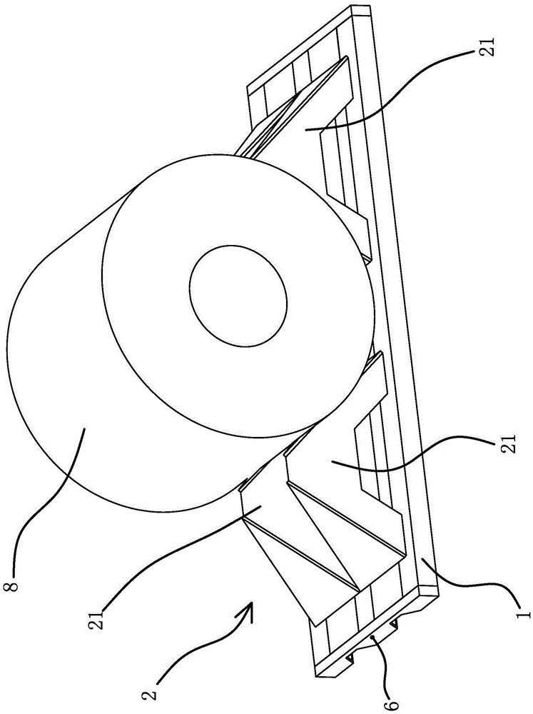
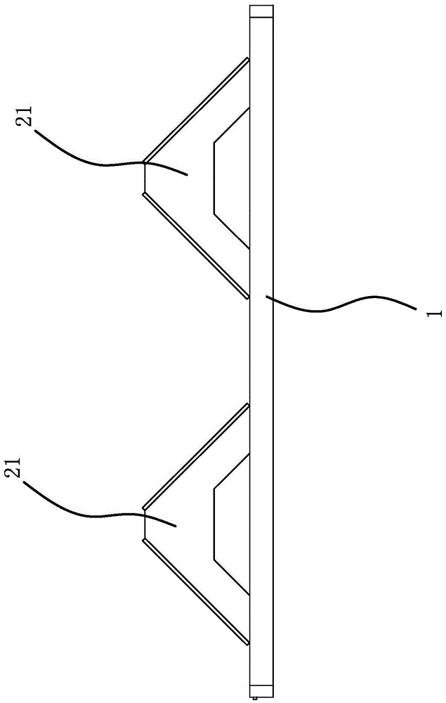
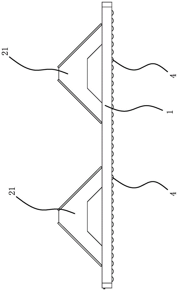
[0036] Such as figure 1 As shown, the pallet used for steel coil transportation includes a pallet frame 1 and a limit frame 2 arranged on the pallet frame 1 for positioning the steel coil 8. The limit frame 2 includes at least two stoppers 21, and the two stoppers 21 A notch for placing the steel coil 8 is formed between them, and the stopper 21 can be in the shape of a triangular platform or a quadrangular platform. In this embodiment, the limit frame 2 has four stoppers 21, and two stoppers 21 form Arranged side by side, the stopper 21 is a hollow structure, and a through hole aligned with the stopper 21 is opened on the pallet rack 1. When transporting the pallet, the pallets can be stacked, and the stopper 21 of the lower pallet can pass through the upper pallet. Through holes for positioning and stacking, reducing the space occupied during transportation.

[0037] Such as Figure 4 to Figure 8 As shown, the bottom of the pallet rack 1 has at least two elongated installa...

Embodiment 2

[0044] The structure and principle of this embodiment are basically the same as that of Embodiment 1. The difference is that at least two airbags are arranged in each installation groove, and the airbags are arranged along the length direction of the installation groove. Justify. When the pallet needs to be moved, the airbags are inflated at the same time, and multiple airbags are inflated at the same time to make the rollers contact the ground and lift the pallet frame off the ground, thereby realizing the movement of the pallet; corresponding airbags are provided at both ends of the roller frame to ensure the stability of the roller frame. The distance between the two ends and the pallet frame remains the same, so that the pallet frame can be kept horizontal when the pallet frame is lifted, so that the steel coil can be stably positioned on the pallet frame.

Embodiment 3

[0046] The structure and principle of this embodiment are basically the same as that of Embodiment 1. The difference is that the guide structure includes several guide rods, which are vertically fixed in the installation groove, and there are a number of guide rods corresponding to the guide rods on the roller frame. hole through which the guide rod passes. The roller frame can only move up and down relative to the pallet frame through the guide rod, so that the pallet frame remains stable when it is lifted off the ground or lowered to the ground, so that the steel coil can be stably positioned on the pallet frame.


PUM


Abstract

The invention provides a tray used for steel coil transportation, and belongs to the technical field of transportation. The tray solves the technical problem that an existing movable tray is not suitable for bearing steel coils. The tray comprises a tray frame and a limiting frame arranged on the tray frame and used for positioning a steel coil. At least two long-strip-shaped installation grooves are formed in the bottom of the tray frame. Long-strip-shaped rolling wheel frames are arranged in the installation grooves. A plurality of rolling wheels are connected to the rolling wheel frames in the length direction of the rolling wheel frame. Guide structures capable of guiding the rolling wheel frames to move up and down relative to the tray frame and limiting structures capable of preventing the rolling wheel frames from being disengaged from the installation grooves are arranged on the portions, located in the installation grooves, on the tray frame. Gas bags are arranged in the installation grooves and located above the rolling wheel frames. The whole rolling wheels can be located in the installation grooves when the gas bags are not inflated. The gas bags can act on the rolling wheel frames to make the rolling wheels stretch out of the installation grooves when the gas bags are inflated and expanded. The tray has the advantage that the steel coil can be stably transported.

Description

technical field [0001] The invention belongs to the technical field of transportation, and relates to a pallet used for steel coil transportation. Background technique [0002] Pallets are a very important tool in the field of logistics. Existing pallets are only used as carriers for stacking goods and facilitating forklift transfer. There are disposable wooden structures and plastic pallets that can be recycled many times. Existing pallets generally have a common defect, that is, they can only be moved or carried by forklifts. When the goods are stacked where forklifts cannot reach, it is difficult to use forklifts to carry mobile pallets, especially for users. It is suitable for pallets for placing heavy goods such as steel coils. Due to the heavy weight of steel coils, it is inconvenient to move with a forklift, especially in the workshop. [0003] For this reason, people have developed a pallet with rollers at the bottom, so that the pallet can be moved without a forkli...

Claims


Application Information

Patent Timeline
Patent Type & Authority Applications(China)
IPC IPC(8): B65D61/00B65D85/66
CPCB65D19/42B65D85/66B65D61/00
Inventor 肖招银牛胜良
Owner ZHEJIANG TOPSUN LOGISTIC CONTROL CO LTD
Learn More