Combustible gas injection system for dual-fuel locomotive

A dual-fuel locomotive and injection system technology, applied in the direction of charging system, combustion engine, internal combustion piston engine, etc., can solve the problems that affect the normal use of the gas system, the difficulty of opening the gas injection rail, and increase the difficulty of maintenance, etc., to reduce heat The effects of dissipation, stable placement, and small heating costs

Inactive Publication Date: 2016-05-25
CHENGDU KELIFU SCI & TECH
View PDF5 Cites 1 Cited by
  • Summary
  • Abstract
  • Description
  • Claims
  • Application Information

AI Technical Summary

Problems solved by technology

[0002] The gas injection rail is a necessary equipment on CNG-gasoline dual-fuel vehicles, but when the temperature is low, the low temperature causes the gas in the low-pressure pipeline to shrink, forming a negative pressure between the gas common rail and the filter, so that the gas injection rail opens It is not easy and affects the normal use of the gas system; we use water heating to heat the gas injection rail to make it work normally, but it is necessary to install a waterway, which increases pipeline interference, is prone to liquid leakage, and increases the difficulty of maintenance

Method used


Image

  • Combustible gas injection system for dual-fuel locomotive
  • Combustible gas injection system for dual-fuel locomotive
  • Combustible gas injection system for dual-fuel locomotive

Examples


Embodiment 1

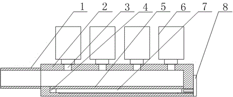
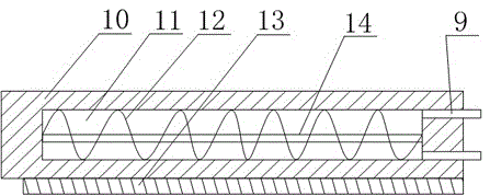
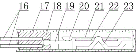
[0022] Such as Figure 1~Figure 3 As shown, this embodiment includes an air intake pipe 1 and a hollow pipe 2 communicating with it. A plurality of injection holes 3 are opened on the upper end of the hollow pipe 2, and a solenoid valve 6 is correspondingly installed on the injection holes 3. The inner wall of the hollow tube 2 is provided with a groove 4 with a superior arc in section, and the injection hole 3 is facing the groove 4, and a plurality of electric heating tubes 7 are arranged side by side in the groove 4, and the electric heating tubes 7, a guide block 13 is installed at the bottom, and a guide groove matching with the guide block 13 is opened at the bottom of the groove 4. The electric heating tube 7 includes a tube body 10, an insulating material 11 filled inside the tube body 10, and a tube The heating wire 12 inside the body 10, the end of the heating wire 12 is connected with a terminal 9, the end of the groove 4 away from the intake pipe 1 has a small hole...


PUM


Abstract

The invention discloses a combustible gas injection system for a dual fuel locomotive. The combustible gas injection system comprises a gas inlet pipe and a hollow pipe, wherein the upper end of the hollow pipe is provided with a plurality of injection holes which are correspondingly provided with solenoid valves; the inner wall of the hollow pipe is provided with grooves; the injection holes are over against the grooves; a plurality of electric heating tubes are arranged in the grooves side by side; the bottom of each electric heating tube is provided with a guide block; the bottom of each groove is provided with a guide groove matched with the guide block; each electric heating tube comprises a tube body, an electric insulating material filled in the tube body and an electric heating wire arranged inside the tube body; the tail end of the electric heating wire is connected with a wiring terminal; one end of the groove far from the gas inlet pipe is provided with a pinhole communicating with the outside; the wiring terminal penetrates through the pinhole and is connected with a wiring plugboard; and a heat conducting board is covered on the open end of each groove. The lower part of the tube body of each electric heating tube is provided with the guide block which is matched with the guide groove, so that the tube body can be mounted more stably; and thus, the electric heating tubes can be fastened without adding any new fixing structure, thereby achieving the goal of optimizing the injection rail internal structure.

Description

technical field [0001] The invention relates to a gas injection rail, in particular to a gas injection system for a dual-fuel locomotive. Background technique [0002] The gas injection rail is a necessary equipment on CNG-gasoline dual-fuel vehicles, but when the temperature is low, the low temperature causes the gas in the low-pressure pipeline to shrink, forming a negative pressure between the gas common rail and the filter, so that the gas injection rail opens It is not easy and affects the normal use of the gas system; we use water heating to heat the gas injection rail to make it work normally, but it is necessary to install a waterway, which increases pipeline interference, is prone to liquid leakage, and increases the difficulty of maintenance. Contents of the invention [0003] The object of the present invention is to provide a gas injection system for a dual-fuel locomotive, which ensures the normal passage of gas and avoids liquid in the gas pipeline. [0004]...

Claims


Application Information

Patent Timeline
Patent Type & Authority Applications(China)
IPC IPC(8): F02M21/02F02M21/06
CPCF02M21/0239F02M21/0245F02M21/0293F02M21/06Y02T10/30
Inventor 胡明容
Owner CHENGDU KELIFU SCI & TECH
Why Eureka
Try Eureka