Split type thermal treatment furnace draught fan

A heat treatment furnace, split technology, applied in liquid fuel engines, mechanical equipment, non-variable-capacity pumps, etc., can solve the problems of scrapping fans, inability to meet heat treatment furnaces, easy high temperature oxidation and corrosion damage, etc., to achieve improved sealing performance, Great practical value, the effect of increasing the service life

Inactive Publication Date: 2016-05-25
HUBEI MILALION METALLURGICAL MACHINERY CO LTD
View PDF7 Cites 0 Cited by
  • Summary
  • Abstract
  • Description
  • Claims
  • Application Information

AI Technical Summary

Problems solved by technology

[0002] The heat treatment furnace fan is an important part of the uniformity of the furnace temperature and atmosphere of the heat treatment equipment, and the coupling end shaft of the heat treatment furnace fan and the fan blade is very easy to be damaged by high temperature oxidation corrosion, and the rotor shaft of the integral heat treatment furnace fan motor and the fan blade shaft are integral, so due to The damage of the end shaft of the fan blade caused the entire fan to be scrapped
[0003] At present, there is a Chinese invention patent with the application number 201210100002.9 disclosing a heat treatment furnace fan that separates the rotating shaft and connects it through a detachable coupling, but it can only meet the demand for easy replacement of parts, and cannot meet the needs of carburizing furnaces. Or the demand for heat treatment furnaces with certain pressure requirements for vacuum furnaces

Method used


Image

  • Split type thermal treatment furnace draught fan
  • Split type thermal treatment furnace draught fan

Examples


Embodiment Construction

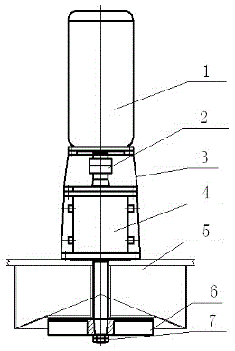
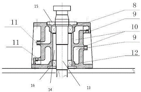
[0020] A split heat treatment furnace fan, such as Figure 1~2 : Including fan motor 1, detachable coupling 2, motor support 3, compartment transmission mechanism 4, furnace body 5, fan blade 6, fan blade fixing nut 7, upper sealing bearing 8, cooling water outlet 9, circulating cooling Water chamber 10, cooling water inlet 11, lower sealed bearing 12, fan shaft 13, lubricating oil chamber 14, upper sealed bearing gland 15, lower sealed bearing gland 16, wherein the fan motor 1 is fixed on the upper part of the motor support 3, and the motor The rotating shaft and the fan rotating shaft 13 are connected by a detachable coupling 2 in the motor support 3, and the fan blade 6 is fixed on the outer end of the fan rotating shaft 13 by a key and the fan blade fixing nut 7, and the motor support 3 and the furnace body 5 are provided with The water-cooled oil lubricated compartment, the upper and lower parts of the water-cooled oil lubricated compartment are respectively fixed with th...


PUM


Abstract

The invention discloses a split type thermal treatment furnace draught fan. The draught fan comprises a draught fan motor, a motor support, a detachable coupling, fan blades, a fan blade fixing nut, a furnace body, a motor rotating shaft and a draught fan rotating shaft, the draught fan motor is fixed to the upper portion of the motor support, the motor rotating shaft and the draught fan rotating shaft are connected in the motor support through the detachable coupling, the fan blades are fixed to the outer end of a draught fan shaft through a key and the fan blade fixing nut, a water-cooling oil-lubricating bay transmission device is arranged between the motor support and the furnace body, the upper portion and the lower portion of the water-cooling oil-lubricating bay transmission device are fixed to the bottom of the motor support and the upper portion of the furnace body through nuts respectively, and the draught fan rotating shaft passes through a water-cooling oil-lubricating bay. According to split type thermal treatment furnace draught fan, the water-cooling oil-lubricating bay is additionally arranged to improve sealing performance of the furnace draught fan, therefore, the furnace draught fan can meet the requirement, for sealing performance, of a carburizing furnace or a vacuum furnace, and meanwhile the modularization maintenance function of the furnace draught fan can be achieved.

Description

technical field [0001] The invention relates to a heat treatment furnace fan, in particular to a split heat treatment furnace fan. Background technique [0002] The heat treatment furnace fan is an important part of the uniformity of the furnace temperature and atmosphere of the heat treatment equipment, and the coupling end shaft of the heat treatment furnace fan and the fan blade is very easy to be damaged by high temperature oxidation and corrosion, and the fan motor rotor shaft of the integral heat treatment furnace is integrated with the fan blade shaft, so due to The damage of the end shaft of the fan blade causes the entire fan to be scrapped. [0003] At present, there is a Chinese invention patent with the application number 201210100002.9 disclosing a heat treatment furnace fan that separates the rotating shaft and connects it through a detachable coupling, but it can only meet the needs of easy replacement of parts, and cannot meet the needs of carburizing furnace...

Claims


Application Information

Patent Timeline
IPC IPC(8): F04D25/08F04D29/053F04D29/054F04D29/64
CPCF04D25/08F04D29/053F04D29/054F04D29/64
Inventor 沈劲松
Owner HUBEI MILALION METALLURGICAL MACHINERY CO LTD
Why Eureka
Try Eureka