
Elastic torque sensor

An elastic torque, sensor technology, applied in the field of sensors, can solve the problems of volume, weight and cost constraints, regular detection and correction, spring failure detection, etc., to achieve the effect of reducing volume and weight, avoiding fatigue fracture, and improving safety

Active Publication Date: 2016-05-25
ZHEJIANG UNIV
View PDF6 Cites 7 Cited by
  • Summary
  • Abstract
  • Description
  • Claims
  • Application Information

AI Technical Summary

Problems solved by technology

However, there are many challenges in material selection, shape design, cold and hot processing technology formulation, and service life of planar torsion springs.
For example, the elastic body (or elastic beam) of the plane torsion spring is prone to fatigue and fracture due to repeated alternating stress; the elastic coefficient of the elastic body (or elastic beam) of the plane torsion spring will change with the use of time. In the control method of SEA or VSA, if the elastic coefficient occurrence rate changes, the torque output at the same angle of rotation will also change. For the planar torsion spring that cannot be corrected for parameters, the above-mentioned problem is how to correct the broken spring. Fault detection, and how to achieve regular detection and correction of spring coefficient, and to ensure precise measurement and precise control
Patent No. CN105058414A proposes a planar torsion spring device with fault detection and parameter correction functions for the above problems, but because the device is an integration of a torque sensor and a planar torsion spring, especially the application of a torque sensor, it has a large volume, Improvements such as weight and cost are limited

Method used


Image

  • Elastic torque sensor
  • Elastic torque sensor
  • Elastic torque sensor

Examples


Embodiment Construction

[0019] The present invention is further described below in conjunction with the accompanying drawings.

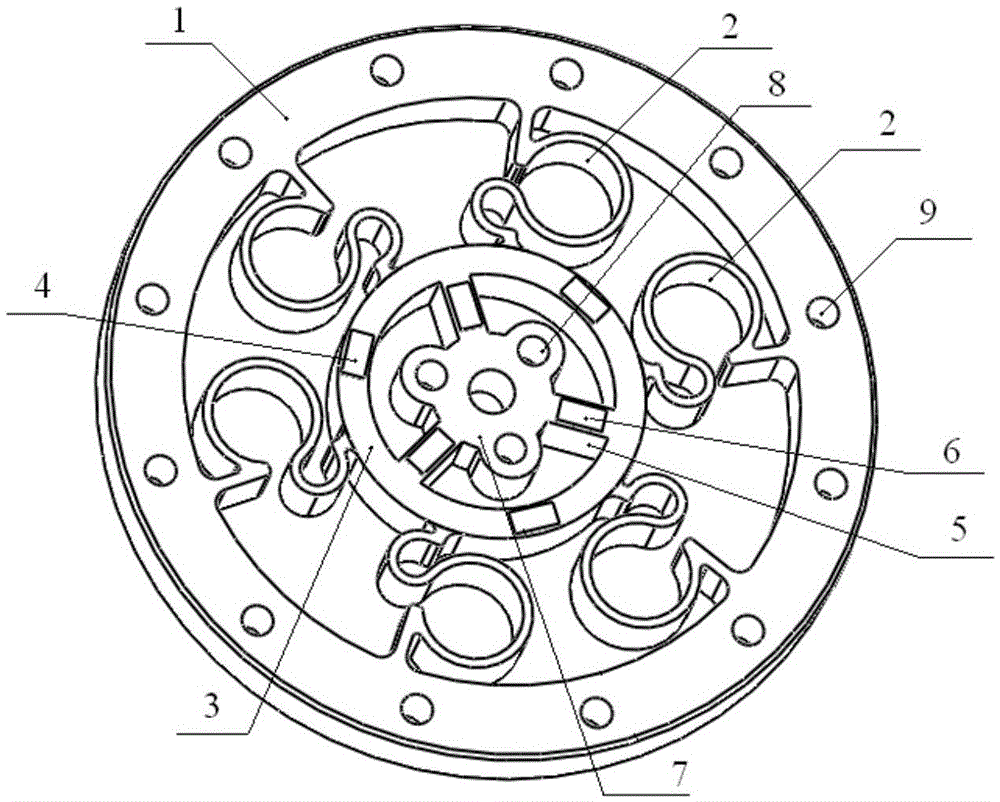
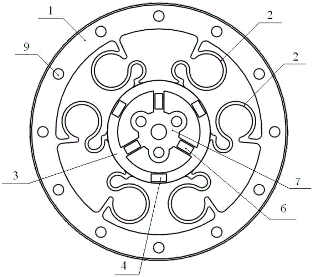
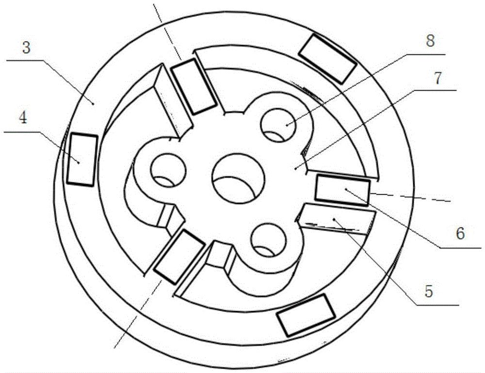
[0020] like Figure 1-5 As shown, the present invention is composed of a sensor outer ring 1, a plurality of elastic bodies 2, an inner sensor ring 3, an inner ring strain gauge 4, a plurality of connecting beams 5, a connecting beam strain gauge 6 and a central base 7; The circumference is evenly distributed, and the two ends are respectively connected to the sensor outer ring 1 and the sensor inner ring 3; each elastic body 2 is composed of two symmetrical elastic body units; connecting beams are evenly arranged between the sensor inner ring 3 and the center base 7 5; the surface of each connecting beam 5 is pasted with connecting beam strain gauges 6, and the connecting beam strain gauges 6 are pasted along the axial direction of the connecting beam 5; the upper and lower surfaces of the sensor inner ring 3 are pasted with inner ring strain gauges 4 , the inner ring str...


PUM


Abstract

The invention discloses an elastic torque sensor. The elastic torque sensor comprises an outer sensor ring, multiple elastic bodies, an inner sensor ring, inner ring strain gauges, connection beams, a connection beam strain gauge and a center base, wherein the multiple elastic bodies are uniformly distributed circumferentially, two ends of the multiple elastic bodies are respectively connected with the outer sensor ring and the inner sensor ring, each elastic body comprises two symmetric elastic body units, the connection beams are uniformly arranged between the inner sensor ring and the center base, surfaces of the connection beams are bonded with the connection beam strain gauge, and upper and lower surfaces of the inner sensor ring are respectively bonded with the inner ring strain gauges uniformly. According to the elastic torque sensor, the peripheral elastic bodies have filtering effects on impact, so short-time impact exerted on the inner torque sensor can be greatly reduced, compared with a traditional torque sensor manufactured by the same material, the elastic torque sensor provided by the invention has remarkable small volume and light weight, moreover, the strain gauge is employed, so use cost can be greatly reduced compared with a commercial torque sensor.

Description

technical field [0001] The invention relates to a sensor, in particular to an elastic torque sensor, which has both physical elasticity and sensing torque. Background technique [0002] With the development of modern science, sensor technology has developed rapidly as an emerging discipline closely related to modern science, and has been widely used in industrial control, transportation, consumer electronics, medical diagnosis, aerospace and other fields, and It also promotes the development of various disciplines. [0003] There are many kinds of sensors and various principles, among which the resistance strain sensor is the most common. In particular, force and torque sensors, as a structural sensor, have been widely used in many fields that need to measure force or torque. Its principle is to use the change of structural parameters to sense and convert signals, while the resistance strain sensor uses the change of resistance when metal materials undergo elastic deformat...

Claims


Application Information

Patent Timeline
IPC IPC(8): G01L3/00
CPCG01L3/00
Inventor 朱秋国熊蓉
Owner ZHEJIANG UNIV
Learn More