
Security fault diagnosis system and method based on Internet of Things

A technology of fault diagnosis system and Internet of Things technology, which is applied in the direction of information technology support system, general control system, control/regulation system, etc., and can solve equipment monitoring, fault detection equipment with high performance requirements, front-end intelligent equipment not working properly, etc. question

Inactive Publication Date: 2016-05-25
广州澳视互动传媒有限公司
View PDF4 Cites 17 Cited by
  • Summary
  • Abstract
  • Description
  • Claims
  • Application Information

AI Technical Summary

Problems solved by technology

[0005] 1. Send the various parameters of the front-end intelligent equipment measured by the sensor to the background processing center, all of which are processed by the background processing center, which not only increases the burden on the background processing center, but also prolongs the time for judging failures. When a serious failure occurs in the equipment, it cannot be dealt with immediately;
[0006] 2. Only the front-end smart devices are monitored, but the devices that supply power to the front-end smart devices are not monitored. In this way, when the power supply equipment fails, the front-end smart devices will not work properly;
[0007] 3. Existing fault detection systems do not take into account the type and severity of faults in front-end intelligent equipment. Some use simple threshold judgment methods to detect faults, and some use modeling algorithms that are too complex to be conducive to real-time detection. The performance requirements of fault detection equipment are relatively high;
[0008] 4. The front-end smart devices directly send the status data collected by the sensor to the back-end processing center through the network. Since the unprocessed status data contains a lot of noise, it not only increases the burden on the network and the back-end processing center, but also affects the accuracy of fault judgment. Accuracy;
[0009] 5. All front-end equipment failures must be handled on site, which increases maintenance costs

Method used


Image

  • Security fault diagnosis system and method based on Internet of Things
  • Security fault diagnosis system and method based on Internet of Things
  • Security fault diagnosis system and method based on Internet of Things

Examples


Embodiment Construction

[0070] The present invention will be described in detail below with reference to the accompanying drawings and examples. It should be noted that, in the case of no conflict, the embodiments in the present application and the features in the embodiments can be combined with each other.

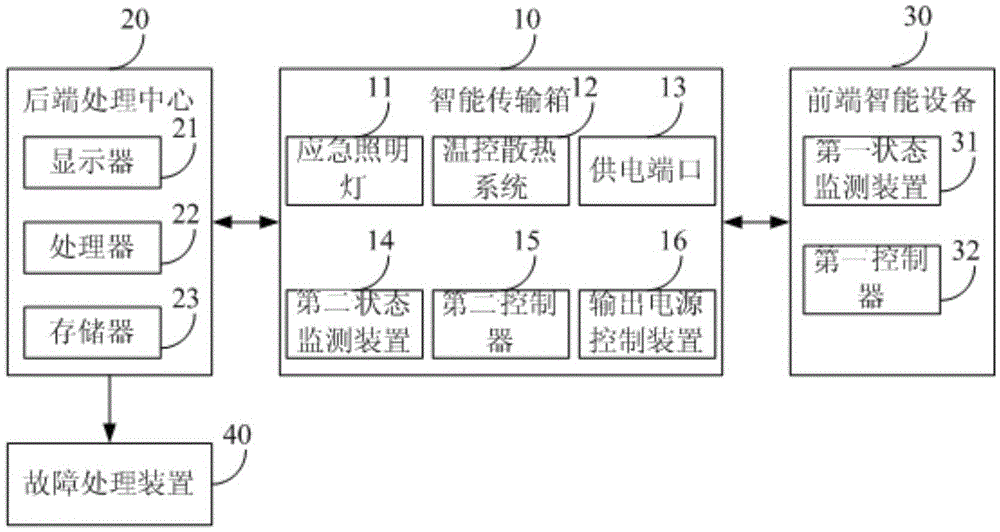
[0071] The invention provides a security fault diagnosis system and method based on Internet of Things technology. Among them, refer to figure 1 , the first aspect provides a security fault diagnosis system based on Internet of Things technology, including:

[0072] The front-end intelligent device 30 is used to collect first state data according to its own state;

[0073] The intelligent transmission box 10 electrically connected with the front-end intelligent device 30 is used to receive the first state data and collect the second state data according to its own state;

[0074] The back-end processing center 20 connected to the intelligent transmission box 10 is used to send working parame...


PUM


Abstract

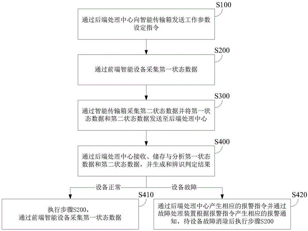
The invention provides a security fault diagnosis system and method based on Internet of Things, an intelligent transmission case is arranged between a front-end intelligent device and a back-end processing center, a first fault diagnosis is performed on the front-end intelligent device by the intelligent transmission case, a power source of the front-end intelligent device can be cut immediately when a major fault occurs, the back-end processing center performs a further fault diagnosis when the major fault does not occur, so that the speed of fault diagnosis is improved, and the burden of the back-end processing center is reduced; besides, the system and the method can monitor and perform fault diagnosis on the working conditions of the intelligent transmission case and the front-end intelligent device, thereby more reliably ensuring normal operation of the front-end intelligent device. According to the invention, the front-end intelligent device with fault can be diagnosed in real time without the user performing an on-site inspection tour, a power supply can be cut remotely and automatically, and the user can be informed that the fault can be pointedly maintained in first time, so that the safety and reliability of the security monitoring system are ensured.

Description

technical field [0001] The present invention relates to the field of security technology, and more specifically, to a security fault diagnosis system and method based on Internet of Things technology. Background technique [0002] The security monitoring system is aimed at preventing and combating illegal crimes. Security monitoring systems are set up in complex public security places, key locations, main streets, places where cases frequently occur, important intersections, checkpoints, etc., and video surveillance images are transmitted to public security at all levels in real time. Government agencies and other relevant departments, through the browsing and recording of image information, enable public security organs at all levels and other relevant departments to intuitively understand and grasp the security dynamics in the monitoring area, and timely and effectively improve the level of social security management. [0003] As we all know, cameras and optical transceive...

Claims


Application Information

Patent Timeline
IPC IPC(8): G05B23/02
CPCG05B23/0208Y04S10/52
Inventor 周维林
Owner 广州澳视互动传媒有限公司
Learn More