
Etching method

A technology to be etched and dry etched, used in the manufacture of electrical components, circuits, semiconductor/solid-state devices, etc. Effect

Active Publication Date: 2016-05-25
INST OF MICROELECTRONICS CHINESE ACAD OF SCI
View PDF5 Cites 7 Cited by
  • Summary
  • Abstract
  • Description
  • Claims
  • Application Information

AI Technical Summary

Problems solved by technology

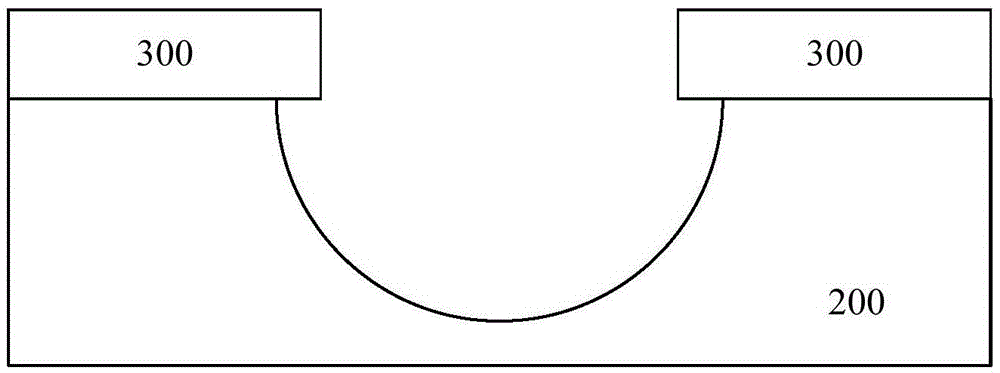
like Figure 4 As shown, under the condition of dry etching, the oblique etching angle can usually be obtained by increasing the overpassivation of the side wall, but the general inclination angle will be greater than 45°, which may not meet the requirements of certain application fields in semiconductor process manufacturing

Method used


Image

  • Etching method
  • Etching method
  • Etching method

Examples


Embodiment Construction

[0022] Hereinafter, embodiments of the present disclosure will be described with reference to the drawings. It should be understood, however, that these descriptions are exemplary only, and are not intended to limit the scope of the present disclosure. Also, in the following description, descriptions of well-known structures and techniques are omitted to avoid unnecessarily obscuring the concept of the present disclosure.

[0023] Various structural schematic diagrams according to embodiments of the present disclosure are shown in the accompanying drawings. The figures are not drawn to scale, with certain details exaggerated and possibly omitted for clarity of presentation. The shapes of the various regions and layers shown in the figure, as well as their relative sizes and positional relationships are only exemplary, and may deviate due to manufacturing tolerances or technical limitations in practice, and those skilled in the art will Regions / layers with different shapes, s...


PUM

PropertyMeasurementUnit
angleaaaaaaaaaa

Abstract

The invention discloses a novel dry etching method, which comprises the following steps: forming a to-be-etched layer on a semiconductor substrate; forming a masking material on the to-be-etched layer; carrying out dry etching on the masking material and the to-be-etched layer; simultaneously carrying out lateral etching (parallel to the surface of the substrate) of a masking layer and longitudinal etching (vertical to the surface of the substrate) of the to-be-etched layer; and obtaining the inclination angle (the included angle between a slope surface and the surface of the substrate) of the corresponding etched slope surface by accurately controlling the speed ratio. The method can flexibly adjust the inclination angle of the etched slope surface within a large range (0-90 degrees), and especially has advantages in the field of the application with a small inclination angle (smaller than 20 degrees) of the etched slope surface in comparison with a conventional etching method.

Description

technical field [0001] The invention relates to the field of manufacturing novel devices of semiconductor integrated circuits, and more specifically relates to an etching method. Background technique [0002] As we all know, thin film growth is a commonly used process in semiconductor manufacturing. It is a challenge to increase the step coverage of film growth on undulating surfaces. Gentle slopes are conducive to improving the coverage of growth on surfaces with steps and undulations. In particular, the step coverage of physical vapor deposition (PVD) process is lower than that of chemical vapor deposition (CVD), but PVD process has its own advantages over CVD process: PVD process adopts physical sputtering, and in principle, the grown film has The characteristics are consistent with the purity of the sputtering target material, but due to the chemical reaction involved in the CVD process, there are incomplete reactants or non-target by-products in the grown film to varyin...

Claims


Application Information

Patent Timeline
Patent Type & Authority Applications(China)
IPC IPC(8): H01L21/3065H01L21/308
CPCH01L21/3065H01L21/3085H01L21/32136H01L21/32139H01L21/3083
Inventor 李俊杰李俊峰杨清华刘金彪贺晓彬
Owner INST OF MICROELECTRONICS CHINESE ACAD OF SCI
Learn More