

An air-gas mixer device for premix burner equipment
A gas mixer and premixed combustion technology, which is applied in the direction of combustion equipment, burners, gas fuel burners, etc., can solve the problems of costing money and time, and achieve the effect of improving capacity
Inactive Publication Date: 2016-05-25
СІТ С П А
View PDF8 Cites 1 Cited by
- Summary
- Abstract
- Description
- Claims
- Application Information
AI Technical Summary
Problems solved by technology
This leads to the large number of configurations available using conventional components, often of relatively large overall dimensions, so that for each installation the positioning of the individual components relative to each other must be custom designed according to the space available, with the result that each specific boiler Provisioning of layouts generally becomes more expensive and time consuming
Method used
View moreImage
Smart ImageViewing Examples

Examples
Embodiment Construction
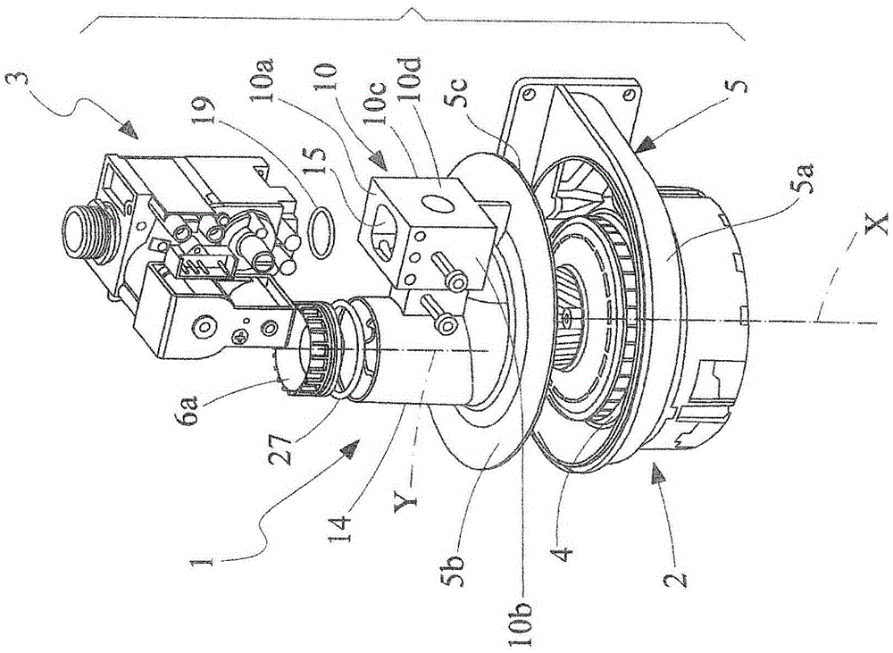
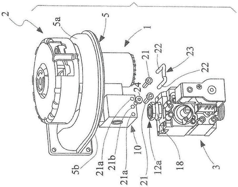
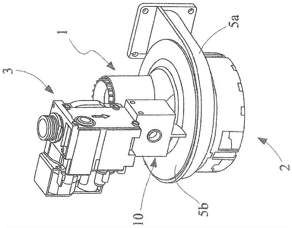
[0027] First refer to figure 1 , reference numeral 1 denotes an air-gas mixer made according to the invention, which is especially designed for burner installations using gas fuel for premixing.
[0028] The device 1 is designed to receive the air flow and the gas flow introduced into the device, and mix the air flow and the gas flow to form an air-gas fuel mixture, ready to be sent to the inlet section 2a of the centrifugal fan 2, which is also designed The air-gas fuel mixture is supplied in delivery mode to the head of a gas burner, not shown in the figure. The invention is particularly, but not exclusively, applicable to the premixing of air and gas for condensing boiler burners.
Login to View More PUM
 Abstract
What is described is an air-gas mixer device for premix burner equipment of boilers, particularly of condensing boilers, comprising flow guide means for guiding an air-gas mixture to the intake section (2a) of a centrifugal fan (2) with an impeller (4) driven in rotation about a first axis (X), the guide means including a tubular Venturi effect conduit structure (6) with contiguous converging and diverging portions (6a, 6b) developed in an axially symmetric manner about a second axis (Y), a section being provided between the portions of conduit into which section the gas flow is delivered for mixing with the air flow supplied through the converging portion (6a) of the conduit. The conduit (6) is in communication with the intake section (2a) of the fan, downstream of the diverging portion (6b) with respect to the direction of the flow, and the impeller (4) of the fan is housed in a scroll manifold (5) including a housing (5a) for receiving the impeller (4) and a cover plate (5b) to close the housing (5a), a through aperture (7) being formed in the cover plate (5b) to put the Venturi effect conduit (6) into communication with the intake section (2a) of the fan. The axis of rotation (X) of the fan (2) does not coincide with the axis (Y) of longitudinal development of the Venturi effect conduit (6), the offset between the first and second axes (X, Y) being chosen so as to allow the mixer device to have a valve unit (3) mounted on it for supplying the gas flow into the Venturi effect conduit (6) with a configuration in which the projection of the overall dimensions of the Venturi effect conduit (6) and of the valve unit (3), in the direction of the axis of rotation (X), lies substantially and predominantly within the projection of the cover plate (5b) of the fan in the direction of the axis of rotation (X).
Description
technical field [0001] The invention relates to an air-gas mixer arrangement for a premix burner installation having the features stated in the preamble of claim 1 , which is the main claim. Background technique [0002] The invention relates in particular to the field of gas burner installations for premix boilers, in which the air-gas mixture is premixed upstream of the combustion head of the burner. [0003] In applications of the type described above, the premixing of air and gas is achieved by means of venturi-effect tubular ducts, where gas is supplied to the constriction of the venturi duct via a valve unit in accordance with the pressure drop signal generated by the air flow. [0004] Premixing is usually also carried out upstream of a fan unit designed to supply a premixed air-gas flow to the burner in delivery mode. [0005] In the applications described above, it is evident that each operating configuration of the entire burner plant assembly requires that the ma...
Claims
Login to View More Application Information
Patent Timeline
 IPC IPC(8): F23D14/36F23D14/64
CPCF23D14/36F23K2900/05002F23D14/62Y02B30/00F23L5/02
InventorA·拉纳利M·兰蒂
OwnerСІТ С П А