Test tube oscillator

An oscillator and test tube technology, applied in the field of medical equipment, can solve the problems of poor oscillation effect, complex structure, and high cost, and achieve the effect of good oscillation effect, simple operation, and low cost

Inactive Publication Date: 2016-06-01
于红艳
View PDF3 Cites 3 Cited by
  • Summary
  • Abstract
  • Description
  • Claims
  • Application Information

AI Technical Summary

Problems solved by technology

Some of the current oscillation operations use human hands to directly shake the test tube. This method is not only troublesome, but also the oscillation effect is not good.
In order to obtain a better vibration effect, some hospitals purchase special oscillators, but the structure is complex and the cost is high

Method used


Image

  • Test tube oscillator
  • Test tube oscillator
  • Test tube oscillator

Examples


Embodiment Construction

[0019] The principles and features of the present invention will be described below with reference to the accompanying drawings. The examples cited are only used to explain the present invention and not used to limit the scope of the present invention.

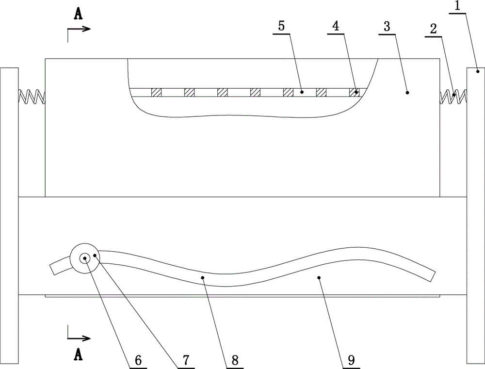
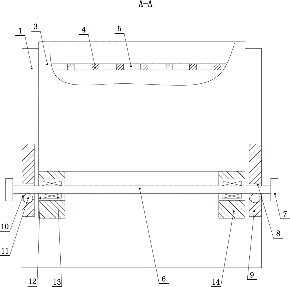
[0020] Such as figure 1 , figure 2 with image 3 As shown, a test tube oscillator includes a vertical plate 1 corresponding to the front and rear. A test tube placement box 3 is fixedly connected between the front and rear vertical plates 1 through a spring 2. Each vertical plate 1 and the test tube placement box 3 are at least One spring 2 is connected. In this embodiment, three springs 2 are connected between the vertical plate 1 and the test tube placement box 3, two of which are located above and one is located below.

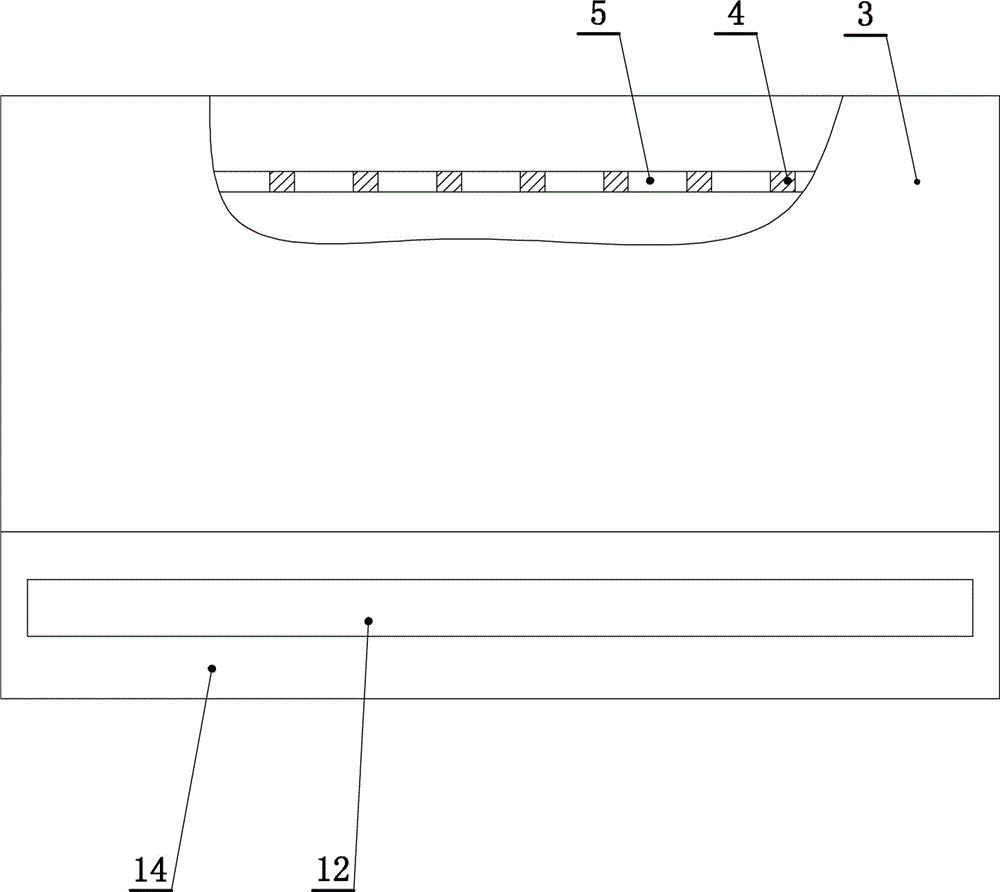
[0021] The test tube placement box 3 is hollow and has an upward opening. The test tube placement box 3 is fixedly connected with a test tube positioning plate 4, and the test tube positioning plate 4 is provid...


PUM


Abstract

The invention discloses a test tube oscillator. A test tube placement box is fixedly connected between two vertical plates front and back via springs, is hollow and is provided with an upward opening; a test tube positioning plate is fixedly connected into the test tube placement box, a plurality of test tube through holes are formed in the test tube positioning plate, baffles which are correspondingly arranged on the left and right sides are respectively fixedly connected between two vertical plates on the left and right sides of the test tube placement box, a push groove is transversely formed in each baffle and is of a wave form, a push rod is movably inserted into the left and right push grooves, and the test tube placement box is erected on the push rod; support plates are fixedly connected to the lower part of the test tube placement box, support grooves are formed in the support plates along the length direction of the support plates, and the push rod passes through the support grooves; inner bearings are in transmission connection to the outside of the push rod in the support grooves; the two support plates are fixedly connected to the lower part of the test tube placement box, and the push rod passes through the left and right support grooves; a plurality of connected pits are formed in the lower sides of the push grooves in a downward sinking manner, balls are arranged in the pits in a rolling manner, and the push rod is in rolling contact with the balls.

Description

Technical field [0001] The invention relates to a medical device, in particular to a test tube oscillator. Background technique [0002] In medical practice, oscillating operations are required in many cases, for example, inspectors oscillate samples, nurses mix solid medicines with liquid medicines and shake them. Some of the current oscillating operations use a human hand to shake the test tube directly. This method is not only troublesome, but also has a poor oscillating effect. In order to obtain a better oscillation effect, some hospitals purchase a dedicated oscillator, but the structure is complex and the cost is relatively high. Summary of the invention [0003] Aiming at the disadvantages, the invention provides a test tube oscillator with simple structure, low price and good use effect. [0004] The technical solutions of the present invention to solve the above technical problems are as follows: [0005] A test tube oscillator includes vertical plates corresponding to th...

Claims


Application Information

Patent Timeline
Patent Type & Authority Applications(China)
IPC IPC(8): B01F11/00
CPCB01F31/20B01F31/201B01F31/26B01F31/24B01F31/70B01F2101/2202B01F2101/23B01F2101/22
Inventor 王倩倩
Owner 于红艳
Why Eureka
Try Eureka