Screw detecting machine

A detection machine and screw technology, which is applied in sorting and other directions, can solve the problems of easily damaged screws under test, and achieve the effects of not being easily damaged, preventing mutual wear, and small vibration

Inactive Publication Date: 2016-06-01
GREE ELECTRIC APPLIANCES INC
View PDF11 Cites 11 Cited by
  • Summary
  • Abstract
  • Description
  • Claims
  • Application Information

AI Technical Summary

Problems solved by technology

[0003] The main purpose of the present invention is to provide a screw detection machine to solve the problem that the measured screw is easily damaged during the detection process of the existing screw detection machine

Method used


Image

  • Screw detecting machine
  • Screw detecting machine
  • Screw detecting machine

Examples


Embodiment Construction

[0029] It should be noted that, in the case of no conflict, the embodiments in the present application and the features in the embodiments can be combined with each other. The present invention will be described in detail below with reference to the accompanying drawings and examples.

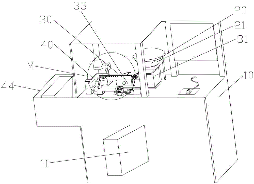
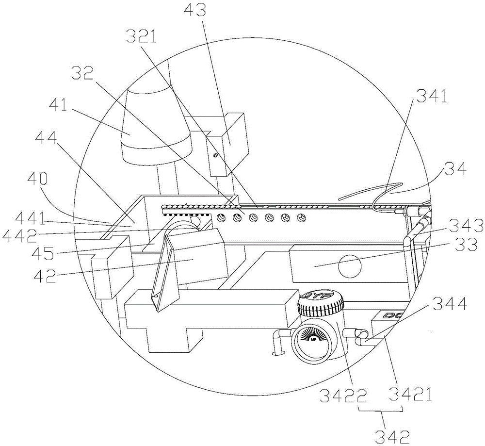
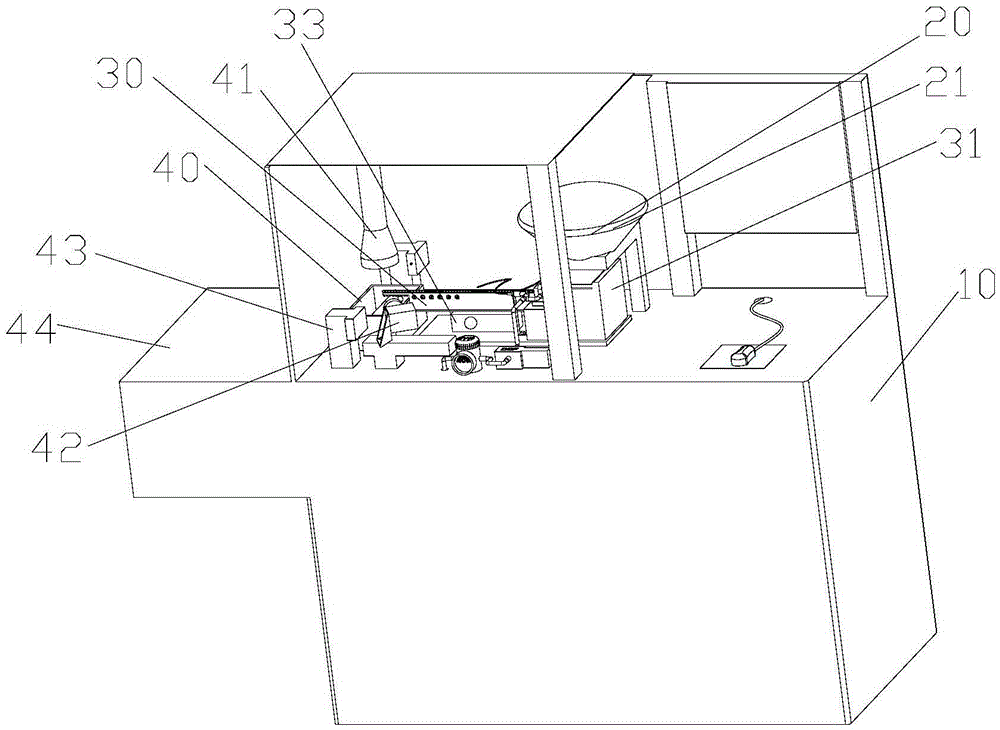
[0030] see Figure 1 to Figure 5 According to the present invention, a screw detection machine is provided, which includes a machine body 10 , a feeding mechanism 20 , a feeding mechanism 30 and a detection recovery mechanism 40 . The feeding mechanism 20 is installed on the machine body 10 for storing and outputting screws. Wherein, the feeding mechanism 30 includes a feeding machine 31 and a conveying assembly, the feeding machine 31 is arranged under the feeding mechanism 20 and the conveying assembly is connected with the feeding machine 31 to convey the screws conveyed by the feeding machine 31 along the first direction. The detecting and recovering mechanism 40 is connected with the con...


PUM


Abstract

The invention provides a screw detecting machine. The screw detecting machine comprises a machine body, a charging mechanism, a feeding mechanism and a detecting and recovering mechanism, wherein the charging mechanism is installed on the machine body and used for storing and outputting screws; the feeding mechanism comprises a feeder and a conveying assembly, the feeder is arranged below the charging mechanism, and the conveying assembly is connected with the feeder so as to convey the screws conveyed by the feeder in the first direction; and the detecting and recovering mechanism is connected with the conveying assembly and used for detecting and recovering the screws conveyed by the conveying mechanism. By the adoption of the mode that the screws are conveyed through the feeder, the screw detecting machine has the characteristic of small vibration, and the problem of mutual abrasion between the screws can be avoided.

Description

technical field [0001] The invention relates to the field of detection equipment, in particular to a screw detection machine. Background technique [0002] At present, the existing screw detection machines on the market are inefficient, and can only detect about 100 screws per minute, and need to use 3 cameras to detect all the information of nut grooves, nuts, and threads. Existing screw detection machines mainly screen materials through a sieving machine, which vibrates greatly, which easily causes mutual abrasion between the screws, and the coating is extremely easy to be damaged, thus causing the screened screws to rust easily. Contents of the invention [0003] The main purpose of the present invention is to provide a screw testing machine to solve the problem that the screw to be tested is easily damaged during the testing process of the existing screw testing machine. [0004] In order to achieve the above object, the present invention provides a screw detection ma...

Claims


Application Information

Patent Timeline
Patent Type & Authority Applications(China)
IPC IPC(8): B07C5/00B07C5/02B07C5/36
CPCB07C5/00B07C5/02B07C5/36B07C5/363
Inventor 陈晓东赵志伟黄才笋余辉苏琪婷刘志高
Owner GREE ELECTRIC APPLIANCES INC
Why Eureka
Try Eureka