Transmission connecting shaft clutch mechanism based on magnetorheological fluid

A magnetorheological fluid, clutch mechanism technology, applied in the direction of fluid clutches, clutches, mechanical equipment, etc., can solve the problems of relative slippage, poor power smoothness and stability, setback, etc., to improve fluency and stability, Avoid the effect of mutual wear

Active Publication Date: 2020-10-13
浙江迅达工业科技股份有限公司
View PDF8 Cites 2 Cited by
  • Summary
  • Abstract
  • Description
  • Claims
  • Application Information

AI Technical Summary

Problems solved by technology

[0004] The present invention provides a transmission-coupling-shaft clutch mechanism based on magnetorheological fluid, which has the advantages of no wear and tear during power separation and combination, sensitive response speed and no frustration, smoothness and smoothness during power transmission. The advantage of high stability solves the problem that in the prior art, multi-plate friction clutch mechanisms are used for power switching, but this multi-plate friction clutch mechanism will wear between the friction plates during engagement, resulting in Th

Method used


Image

  • Transmission connecting shaft clutch mechanism based on magnetorheological fluid
  • Transmission connecting shaft clutch mechanism based on magnetorheological fluid
  • Transmission connecting shaft clutch mechanism based on magnetorheological fluid

Examples


Example Embodiment

[0019] The technical solutions in the embodiments of the present invention will be clearly and completely described below in conjunction with the accompanying drawings in the embodiments of the present invention. Obviously, the described embodiments are only a part of the embodiments of the present invention, rather than all the embodiments. Based on the embodiments of the present invention, all other embodiments obtained by those of ordinary skill in the art without creative work shall fall within the protection scope of the present invention.
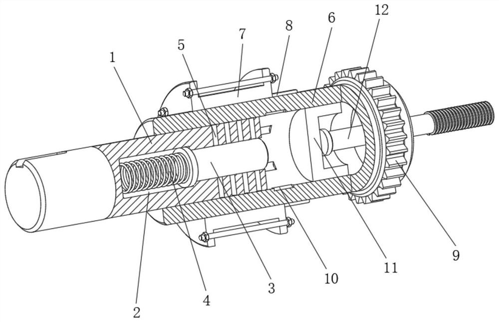
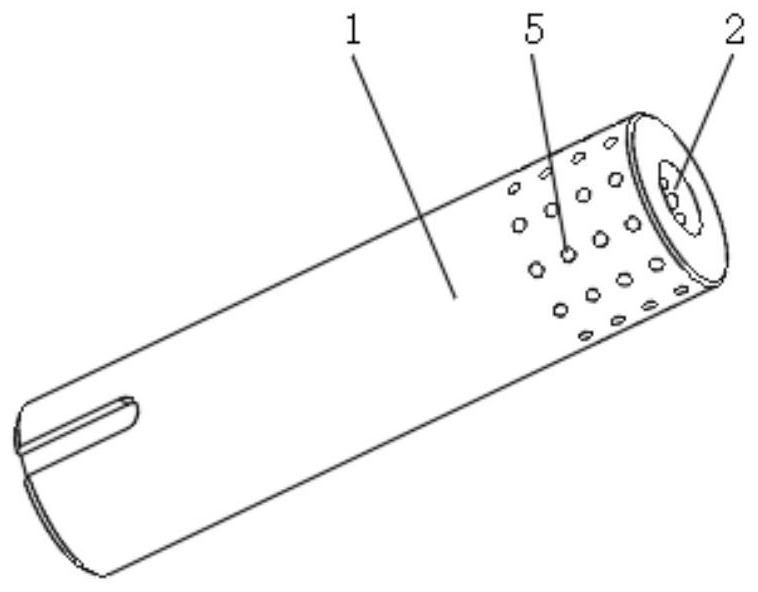
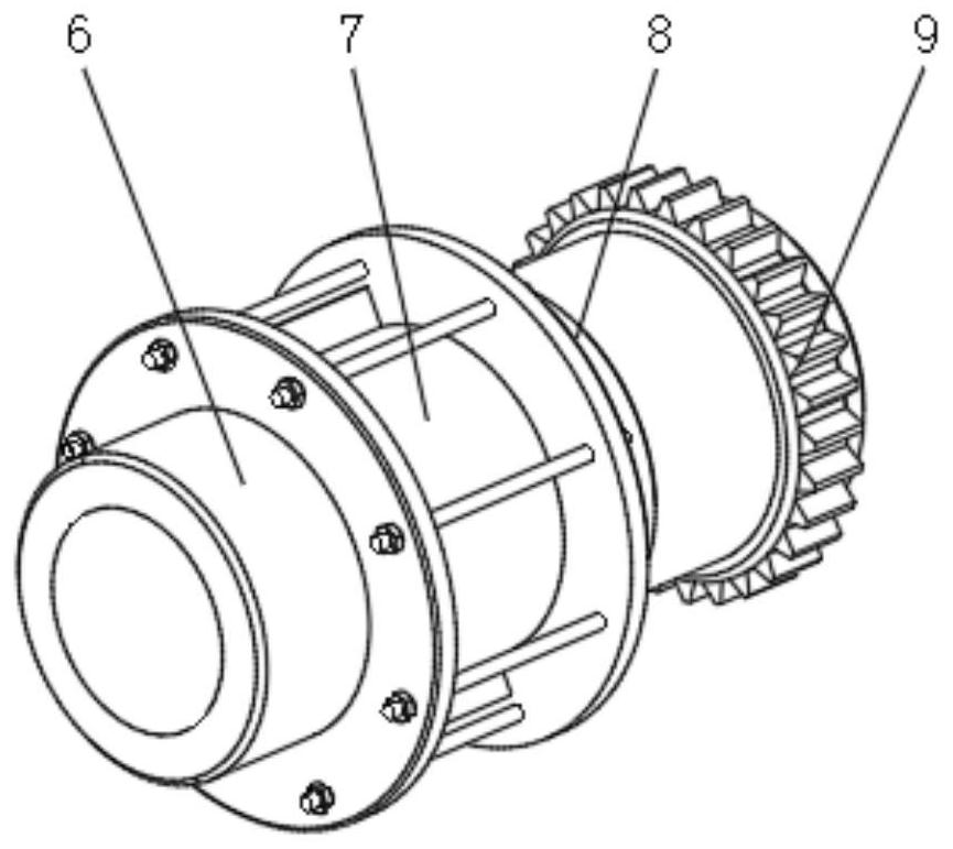
[0020] See Figure 1-3 , A transmission coupling clutch mechanism based on magnetorheological fluid, including a transmission spindle 1, a side of the middle of the inner cavity of the transmission spindle 1 is provided with a mounting inner groove 2, and the inner wall of the mounting inner groove 2 is movably sleeved with a movable pressing rod 3 , And the movable pressure rod 3 and the side of the inner wall of the inner groove 2 are ...


PUM


Abstract

The invention relates to the technical field of clutch transmission mechanisms, and discloses a transmission connecting shaft clutch mechanism based on a magnetorheological fluid. The mechanism comprises a transmission main shaft, wherein a mounting inner groove is formed in one side of the middle of an inner cavity of the transmission main shaft, a movable pressing rod is movably arranged on theinner wall of the mounting inner groove in a sleeve mode, the movable pressing rod is in transmission connection with one side of the inner wall of the mounting inner groove through a reset spring, atransmission groove hole is formed inside one side of the outer surface of the transmission main shaft, and an electromagnetic coil is fixedly mounted on the left side of the outer surface of a transmission driven shaft and located on the outer edge of the transmission groove hole. According to the transmission connecting shaft clutch mechanism based on the magnetorheological fluid, through arrangement of the mounting inner groove, the movable pressing rod and the reset spring, a magnetorheological fluid on one side of the inner cavity of the transmission main shaft can be discharged out of the transmission main shaft when power is separated, so that damping friction caused by the magnetorheological fluid in a suspension state to the transmission main shaft is reduced, and then friction loss of the transmission main shaft when power is transmitting is reduced.

Description

technical field [0001] The invention relates to the technical field of clutch transmission mechanisms, in particular to a transmission coupling shaft clutch mechanism based on magneto-rheological fluid. Background technique [0002] As a common component in mechanical transmission, the clutch mechanism can separate and engage the power in the transmission system at any time, and then effectively control and adjust the power output of the engine or motor. At present, in the prior art, the power Most of the switching uses a multi-plate friction clutch mechanism, but this multi-plate friction clutch mechanism will have wear between the friction plates during engagement, which will cause the gap between the friction plates to become larger, thereby prolonging the power during engagement. The length of time, and due to the wear of the friction plate will produce a large amount of powder, which cannot be cleaned in time and adheres to the friction plate, resulting in the deteriora...

Claims


Application Information

Patent Timeline
IPC IPC(8): F16D37/02
CPCF16D37/02
Inventor 黄剑
Owner 浙江迅达工业科技股份有限公司
Why Eureka
Try Eureka