Anti-displacement cold stamping drawing mold

A drawing die and cold stamping technology, which is applied in the field of anti-tampering cold stamping drawing dies, can solve the problems of limited anti-tampering ability, no convenient positioning structure, insufficient stability of the working process, etc., and achieve the effect of maintaining smoothness

Active Publication Date: 2016-06-01
NINGBO YUANJING AUTO PARTS +1
View PDF7 Cites 9 Cited by
  • Summary
  • Abstract
  • Description
  • Claims
  • Application Information

AI Technical Summary

Problems solved by technology

The disadvantage of this utility model is that there is no convenient positioning structure, the anti-tampering ability is limited during the delay, and the stability of the working process is insufficient.

Method used


Image

  • Anti-displacement cold stamping drawing mold
  • Anti-displacement cold stamping drawing mold
  • Anti-displacement cold stamping drawing mold

Examples


Embodiment 1

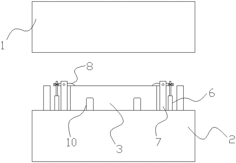
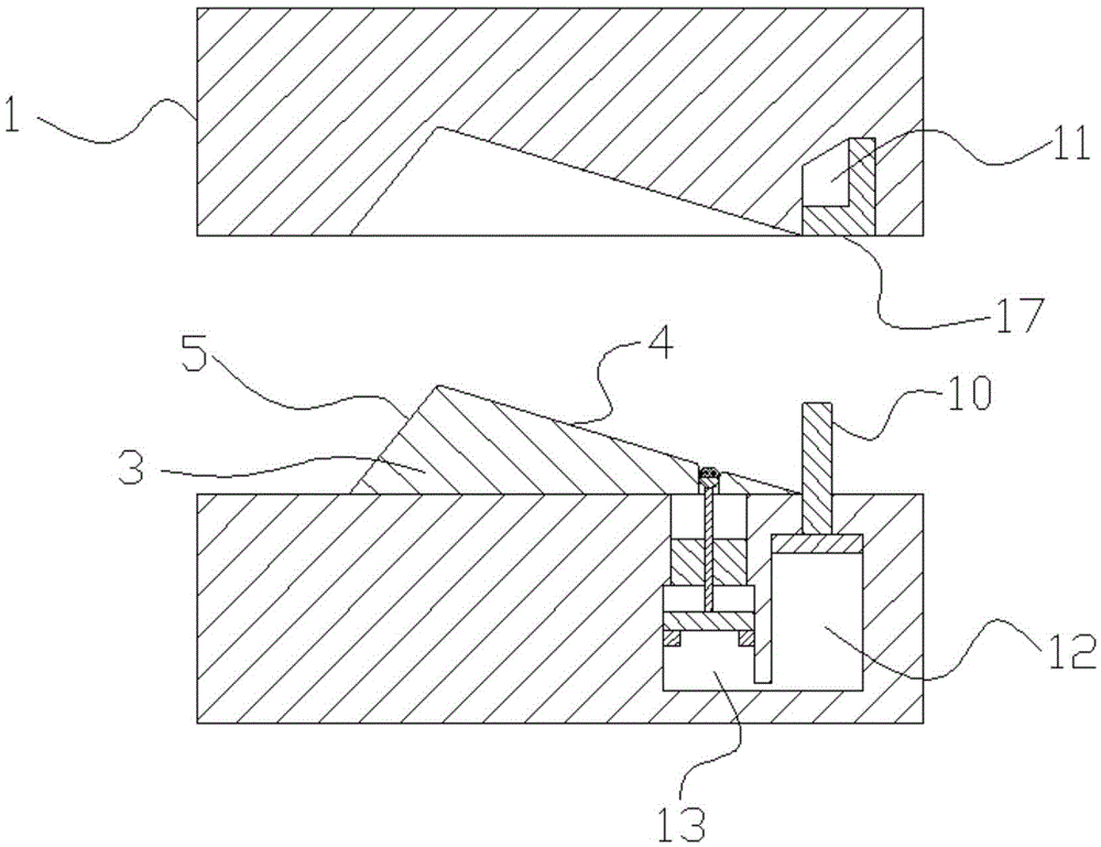
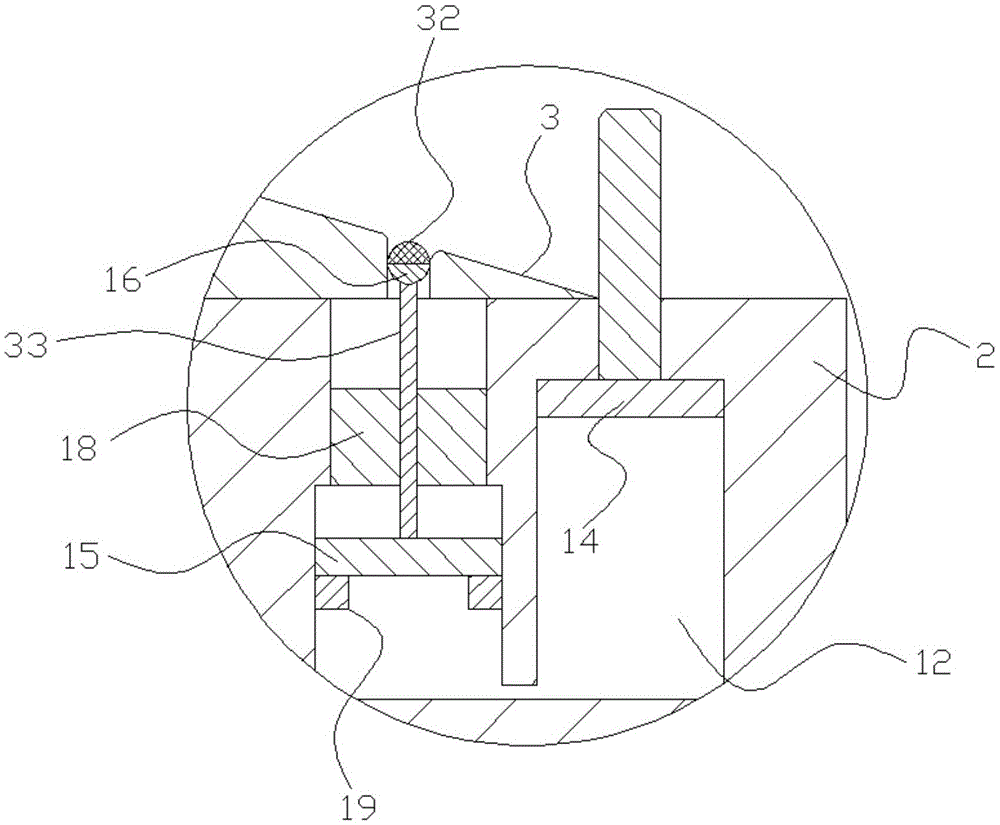
[0022] Embodiment 1: as figure 1 , figure 2 , image 3 , Figure 4 In the illustrated embodiment, a tamper-proof cold stamping drawing die includes a die 1 above and a punch 2 below, and the die includes a table 3, and the table has Long inclined profile 4, short inclined profile 5, the junction of the long inclined profile and the short inclined profile is the top section, the punch is provided with a plate cavity, the punch, the die After closing the mold, the remaining space left in the concave cavity of the plate is the mold cavity. The concave mold is provided with several pre-limiting parts, and the pre-limiting parts include a pre-limiting cylinder 6 and a positioning frame 7. , the piston rod of the pre-limiting cylinder faces upwards, and the positioning frame is provided with a bezel 8 whose middle part is rotatably connected with the locating frame. A horizontal sliding hole is provided, and the horizontal sliding hole 31 is provided with a rotating shaft 9. Th...

Embodiment 2

[0025] Embodiment 2: the basic structure and implementation mode of this embodiment are the same as embodiment 1, and its difference is, as Figure 5 As shown in , the plate retaining column is provided with a plate hole 20, a plate 21 passes through the plate hole, one end of the plate is provided with a plate pressure head 22 for pressing the plate, and the other end is connected to One end of a high-elastic extension spring 23, the lower surface of the described pressing plate is provided with an anti-pullback protrusion 24, and the described punch is provided with a limit slide block 25 and a slide block groove 26. The slider can slide up and down in the slider groove, and the slider groove is provided with some top block springs 27 for resisting the limit slider, and the limit slider is provided with a through hole 28, and The anti-pullback limiting groove corresponding to the anti-pullback protrusion, the anti-pullback limiting groove is located below the passing hole an...


PUM


Abstract

The invention discloses an anti-displacement cold stamping drawing mold, and aims to provide a drawing mold capable of effectively and quickly positioning a drawing plate, effectively protecting the plate and guaranteeing the finished product quality. The anti-displacement cold stamping drawing mold comprises a concave mold positioned on the upper side, and a convex mold positioned on the lower side; the concave mold includes a molding table; a plate cavity is formed in the convex mold; multiple pre-limiting parts are arranged on the concave mold; the pre-limiting parts include pre-limiting cylinders and positioning frames; the positioning frames are provided with pressing bars rotationally connected with the positioning frames through middle parts; transverse slide holes are formed in the pressing bars; rotating shafts are arranged in the transverse slide holes; piston rods of the pre-limiting cylinders are rotationally connected with the rotating shafts; and a pre-limiting anti-interference cavity is formed in the concave mold. The anti-displacement cold stamping drawing mold has the following beneficial effects: the anti-displacement cold stamping drawing mold can provide effective clamping and fixation to guarantee smooth actuation of previous drawing process, has an automatic ejecting structure for automatically realizing ejection after mold separation, and can continuously fix the plate after failure of a pre-positioning structure to realize automatic deviation when the mold is to be closed, so that the smoothness of mold closing process is maintained.

Description

technical field [0001] The invention belongs to the technical field of drawing dies, in particular to an anti-tampering cold stamping drawing die. Background technique [0002] There are many types of cold stamping dies, ranging from simple inner panel dies to large outer cover dies, and drawing dies, or drawing dies, are also commonly used. In automobile production, it is often necessary to stretch out L-shaped or similar L-shaped panels. However, this type of plate often has the phenomenon of part stringing in production. The reason for the problem is that the common material steel plate is straight, but the cross-sectional shape of the mold table of this type of plate or plate is close to L-shaped. When the flat After the straight plate is placed on the mold, there will be a section of the plate warped. The mold forms the plate by clamping the upper and lower molds. When the upper mold moves downward, the lower surface first contacts the plate with a relatively high warp...

Claims


Application Information

Patent Timeline
Patent Type & Authority Applications(China)
IPC IPC(8): B21D37/10B21D22/20B21D43/00B21D45/04B21D55/00
CPCB21D22/20B21D37/10B21D43/003B21D45/04B21D55/00
Inventor 陈敬国
Owner NINGBO YUANJING AUTO PARTS
Why Eureka
Try Eureka