A control method and equipment for seaming centering of thin strip steel in continuous annealing furnace

A continuous annealing furnace and control method technology, applied in the field of strip rolling, can solve problems such as the risk of broken strips and poor alignment accuracy of the unit, and achieve the effects of reducing the risk of broken strips, improving stitching precision, and smooth production

Active Publication Date: 2017-08-25
BAOSHAN IRON & STEEL CO LTD
View PDF6 Cites 1 Cited by
  • Summary
  • Abstract
  • Description
  • Claims
  • Application Information

AI Technical Summary

Problems solved by technology

[0005] The object of the present invention is to provide a control method and equipment for seaming centering of thin strip steel in a continuous annealing furnace. One hydraulic cylinder for traversing and one hydraulic cylinder for rotating. The strip is adjusted through the rotating hydraulic cylinder and the hydraulic cylinder for traversing, and the strip is controlled to be aligned and centered. At the center of the unit, the edge measuring device mainly detects whether the forward strip and the rear strip are aligned, improves the alignment accuracy, and reduces safety hazards, and is used to solve the poor alignment accuracy of the existing control method and the unit has broken strips risk technical issues

Method used


Image

  • A control method and equipment for seaming centering of thin strip steel in continuous annealing furnace
  • A control method and equipment for seaming centering of thin strip steel in continuous annealing furnace
  • A control method and equipment for seaming centering of thin strip steel in continuous annealing furnace

Examples


Embodiment Construction

[0032] The present invention will be described in further detail below in conjunction with the accompanying drawings.

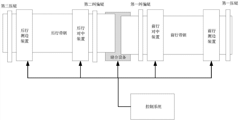
[0033] Such as figure 1 As shown, the control device of the present invention is provided with a first pressure roller at the head of the forward strip, and a second pressure roller is provided at the tail of the trailing strip, and the first pressure roller and the second pressure roller are lifted at ordinary times. When carrying out the centering operation, the first pressure roller and the second pressure roller are pressed down, and the bottom frames of the first pressure roller and the second pressure roller are fixed, and only play the effect of fixing the strip steel.

[0034] A first deviation-correcting roller is arranged at the tail of the forward strip, and a second deviation-correcting roller is arranged at the head of the trailing strip, and the bottom frames of the first deviation-correcting roller and the second deviation-correcting roller are...


PUM


Abstract

The invention relates to the technical field of strip steel rolling, in particular to a control method and equipment for stitching centering of thin strip steel in a continuous annealing furnace. The present invention adopts a set of centering devices and a set of side measuring devices before and after the sewing equipment. Whether the running strip and the rear strip are aligned, that is, whether the centerline of the strip is parallel to the centerline of the unit. At the same time, a transverse hydraulic cylinder and a rotary hydraulic cylinder are respectively installed at the front and rear of the sewing equipment. Through the cooperation of the first deviation correction roller and the second deviation correction roller, the front and rear strips of the sewing equipment can be aligned and centered, which can greatly improve the sewing quality. Accuracy, reduce the risk of belt breakage of the unit, and make production run more smoothly. The invention solves the technical problem that the stitching accuracy of the existing control method is poor, especially when the width of the front and rear strips is inconsistent, and there is a risk of strip breakage.

Description

technical field [0001] The invention relates to the technical field of strip steel rolling, in particular to a control method and equipment for stitching centering of thin strip steel in a continuous annealing furnace. Background technique [0002] The cold-rolling and pickling units of major domestic steel mills have designed long production lines, which are extremely difficult to control. This is mainly reflected in the fact that the strip running on the production line in continuous production should be controlled within a certain horizontal range. It may cause damage to the product or damage to the production equipment, so that the production cannot be carried out. In order to avoid the deviation of the strip steel, a strip centering device is installed at an appropriate position on the production line so that the strip steel can be guaranteed to be on the center line of the unit, and the centering device Mounted on a measuring frame, the strip passes through the measuri...

Claims


Application Information

Patent Timeline
Patent Type & Authority Patents(China)
IPC IPC(8): B21D39/02B21D43/00B21C51/00
Inventor 童显威刘永锋李典华何小丽
Owner BAOSHAN IRON & STEEL CO LTD
Why Eureka
Try Eureka