Guiding mechanism

A technology of guiding mechanism and telescopic mechanism, which is applied in the field of machine tools, can solve problems such as winding and deviation, tool broken belt, etc., and achieve the effect of reducing the risk of broken belt

Inactive Publication Date: 2021-03-12
马鞍山海森控电气有限公司
View PDF6 Cites 0 Cited by
  • Summary
  • Abstract
  • Description
  • Claims
  • Application Information

AI Technical Summary

Problems solved by technology

[0003] During use, these tools can only work by tension, but if the tool is too long, it will receive the reaction force of the workpiece during processing, causing bending and deviation, and the tool may easily break.

Method used


Image

  • Guiding mechanism
  • Guiding mechanism
  • Guiding mechanism

Examples


Embodiment

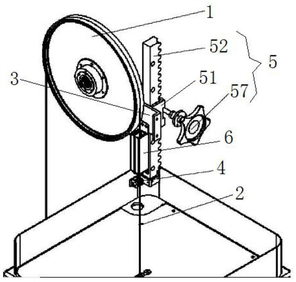
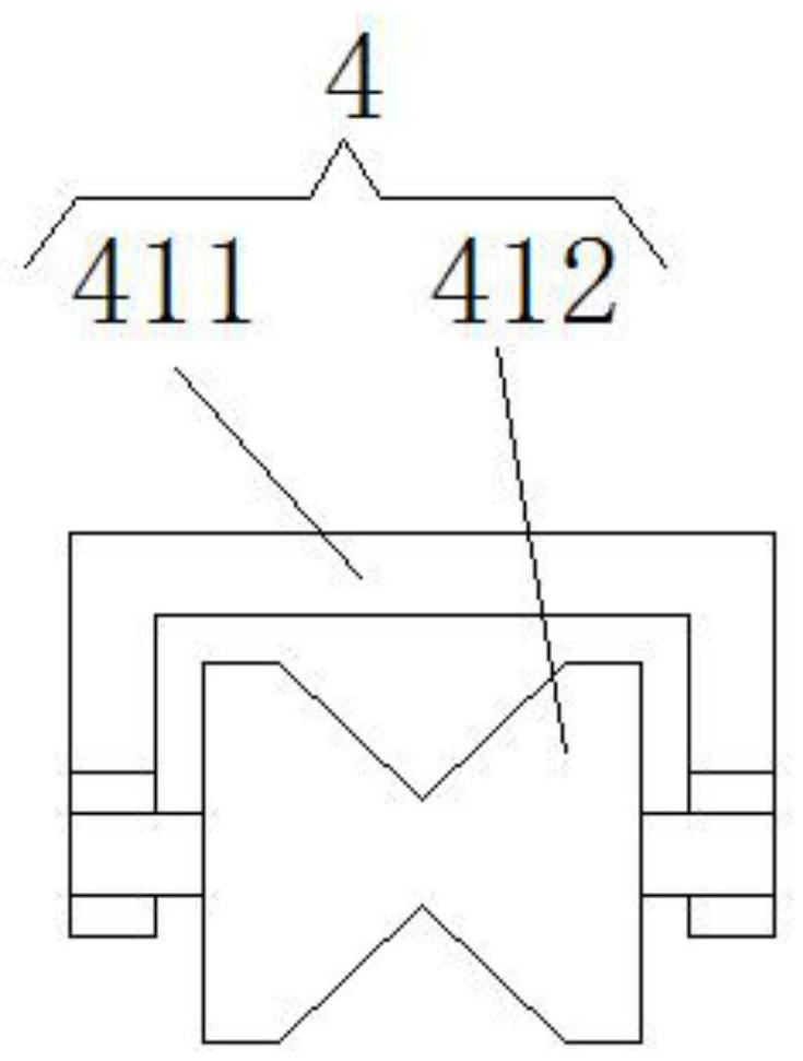
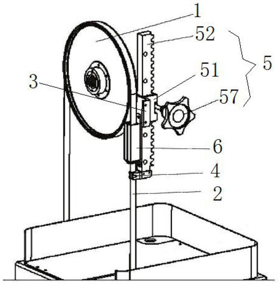
[0026] Such as Figure 1-9 As shown, the guide mechanism, the guide mechanism is installed on the sawing machine, a pair of runners 1 are arranged on the sawing machine, and a tool belt 2 is tightened on the pair of runners 1, and the guide mechanism includes one end fixed on the frame The mounting plate 3 on the top, the mounting plate 3 is arranged parallel to the runner 1, and the other end of the mounting plate 3 extends to the side of the tool belt 2 driven by the runner 1, and the vertical direction is installed on the mounting plate 3 The bottom end of the telescopic mechanism 5 in the vertical direction is a moving end, and the bottom end of the telescopic mechanism 5 in the vertical direction is fixedly connected with a guide unit 4 that cooperates with the tool belt 2 . The guide mechanism proposed by the technical solution can reduce the vibration frequency and amplitude of the part of the tool belt not in contact with the runner by setting the guide unit, thereby r...


PUM


Abstract

The invention discloses a guide mechanism which is mounted on a sawing machine. A pair of rotating wheels are arranged on the sawing machine; a tool belt is tightened on the pair of rotating wheels; the guide mechanism comprises a mounting plate with one end fixed to a rack; the mounting plate is parallel to the rotating wheels, and the other end of the mounting plate extends to one side of the tool belt driven by the rotating wheels; a telescopic mechanism in the vertical direction is mounted on the mounting plate; the bottom end of the telescopic mechanism in the vertical direction is a movable end; and the bottom end of the telescopic mechanism in the vertical direction is fixedly connected with a guide unit matched with the tool belt. According to the guide mechanism, the vibration frequency and amplitude of the part, not making contact with the rotating wheels, of the tool belt can be reduced through the guide unit, and therefore the belt breaking risk is reduced.

Description

technical field [0001] The invention belongs to the technical field of machine tools, and in particular relates to a guiding mechanism of a multifunctional machine tool. Background technique [0002] Corresponding to the processing requirements of different materials, machine tools require different processing tools. For example, straight cutting requires a saw band; grinding and polishing requires an abrasive belt; curved cutting requires a wear-resistant steel wire coated with diamond particles. [0003] During use, these tools can only work by tension, but if the tool is too long, it will receive the reaction force of the workpiece during processing, causing bending and deviation, and the tool may be prone to belt breakage. Contents of the invention [0004] The present invention provides a guide mechanism for the problems of the above-mentioned prior art. [0005] The present invention realizes solving above-mentioned technical problem by following technical means: ...

Claims


Application Information

Patent Timeline
Patent Type & Authority Applications(China)
IPC IPC(8): B23D55/08B23D57/00B24B21/18B24B21/20
CPCB23D55/08B23D57/0061B24B21/20B24B21/18Y02P70/10
Inventor 于彦奇
Owner 马鞍山海森控电气有限公司
Why Eureka
Try Eureka