Pressurization control method and pressurization control system for rotary drilling rig

A technology of rotary drilling rig and control system, which is applied to the automatic control system of drilling, drilling equipment, earthwork drilling and mining, etc. It can solve problems such as open welding of the square head, damage of structural parts, and drop of the drill bit, so as to avoid operation delay , the effect of reducing the vibration frequency

Active Publication Date: 2013-12-11
SHANGHAI ZOOMLION HEAVY IND PILING MACHINERYCO +1
View PDF8 Cites 6 Cited by
  • Summary
  • Abstract
  • Description
  • Claims
  • Application Information

AI Technical Summary

Problems solved by technology

The eccentric load of the drill bit 4 will generate vibration, and the drill bucket 3, drill pipe 1, power head and follower frame will also bear the corresponding eccentric load and corresponding vibration, causing damage to the corresponding structural parts
The greater the eccentric load, the higher the vibration frequency and the greater the impact load on the structural parts. In

Method used


Image

  • Pressurization control method and pressurization control system for rotary drilling rig
  • Pressurization control method and pressurization control system for rotary drilling rig
  • Pressurization control method and pressurization control system for rotary drilling rig

Examples


Embodiment Construction

[0027] Specific embodiments of the present invention will be described in detail below in conjunction with the accompanying drawings. It should be understood that the specific embodiments described here are only used to illustrate and explain the present invention, and are not intended to limit the present invention.

[0028] In the present invention, unless otherwise specified, the used orientation words such as "upper and lower" are words used to describe the mutual positional relationship between the various components of the rotary drilling rig under normal working conditions.

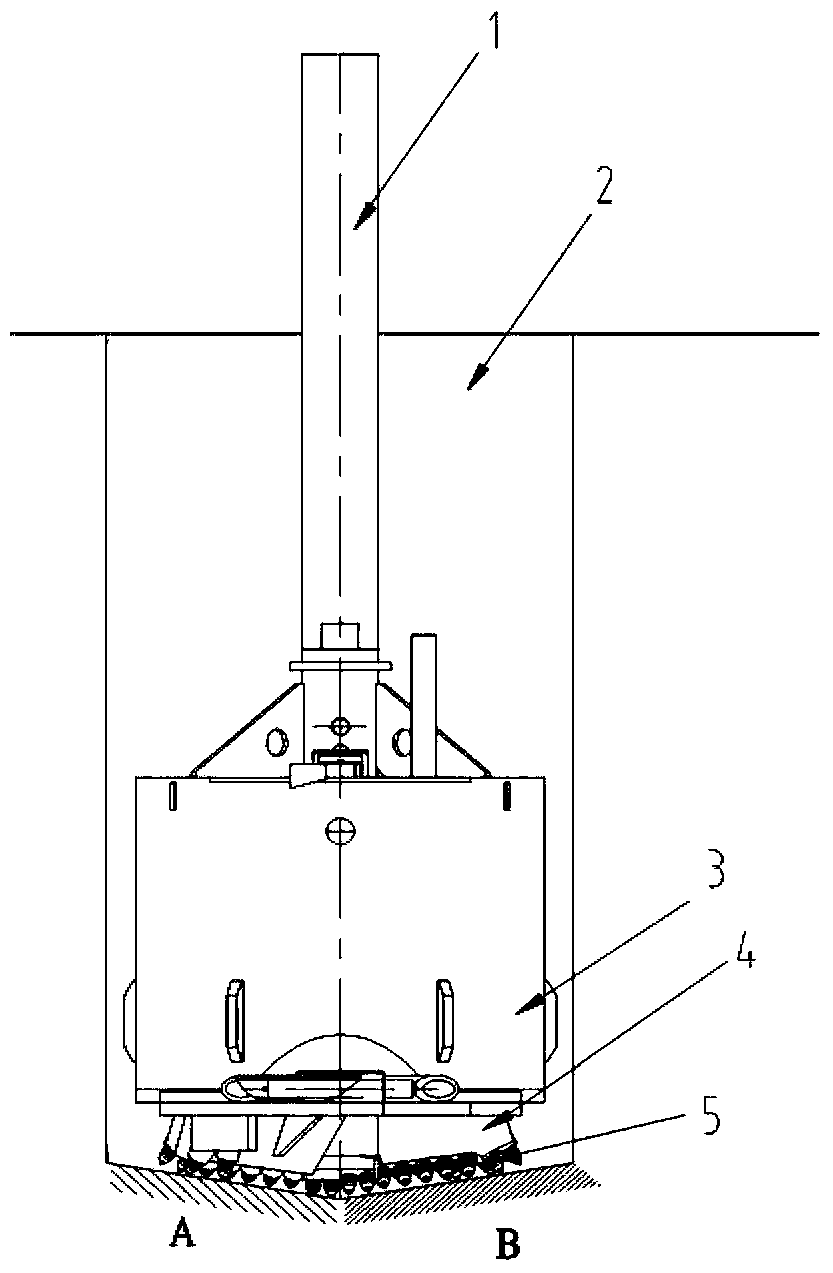
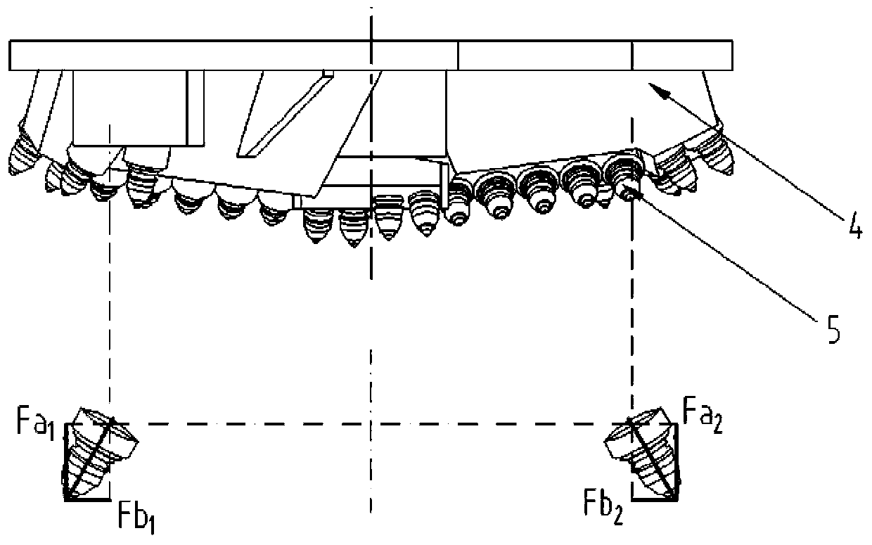
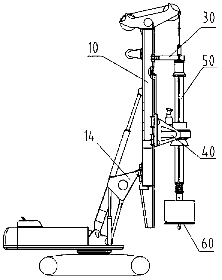
[0029] Generally, a rotary drilling rig includes a mast 10, a left mast oil cylinder 11, a right mast oil cylinder 16, a drill pipe 50, a main winch (not shown) for controlling the rise or fall of the drill pipe 50, and a traveling frame connected with the drill pipe 50. 30 and power head 40, pressurized oil cylinder 20 for power head 40 pressurization, and parts such as drill bit 60. For the work...


PUM


Abstract

The invention discloses a pressurization control method and a pressurization control system for a rotary drilling rig. The pressurization control method for the rotary drilling rig includes the following steps that the pressure value of a rodless cavity of a left mast oil cylinder (11) and the pressure value of a rodless cavity of a right mast oil cylinder (16) are obtained respectively; a controller processes the pressure value of the rodless cavity of the left mast oil cylinder (11) and the pressure value of the rodless cavity of the right mast oil cylinder (16) to obtain the pressure difference value of the rodless cavity of the left mast oil cylinder (11) and the rodless cavity of the right mast oil cylinder (16); the pressure of a rodless cavity of a pressurization oil cylinder (20) is controlled according to the relationship of a preset pressure difference value and the pressure value of the rodless cavity of the pressurization oil cylinder (20). The pressurization control method for the rotary drilling rig can automatically adjust pressure applied to a power head by the pressurization oil cylinder, reduces the probability of drilling stem unbalance loading and mast unbalance loading caused when a drill bit impacts a load and a load is unbalance, lowers vibration frequency, and operating mechanism damage caused by factors such as human judging errors or operating delay and personal and equipment safety accidents caused due to the facts that damaged parts fall from a high altitude are avoided.

Description

technical field [0001] The invention relates to the technical field of engineering machinery, in particular to a pressurization control method and a pressurization control system of a rotary drilling rig. Background technique [0002] Rotary drilling rig is currently the most widely used pile foundation equipment, please refer to figure 1 , the working process is that the drill bit 4 descends with the drill rod 1 to the working position at the bottom of the pile hole 2, the hydraulic motor drives the drill rod 1 to rotate, the drill rod 1 is connected with the drill bit 4 through the connecting square head, and the drill rod 1 drives the drill teeth of the drill bit 4 5 cutting and drilling operations. In drilling conditions, the pressurized oil cylinder applies a certain amount of downward pressure to the power head, and the piston rod of the pressurized oil cylinder stretches out to drive the power head, drill pipe, and drill bit to move downward. [0003] The drill toot...

Claims


Application Information

Patent Timeline
IPC IPC(8): E21B44/06
Inventor 肖定成黄志明吴越策何欢
Owner SHANGHAI ZOOMLION HEAVY IND PILING MACHINERYCO
Why Eureka
Try Eureka