Organic compound, application thereof and organic light-emitting device adopting compound
What is AI technical title?
AI technical title is built by PatSnap AI team. It summarizes the technical point description of the patent document.
An organic compound and heteroaryl technology, applied in the field of organic electroluminescence, to achieve the effects of high luminous efficiency, excellent service life, and low starting voltage
Pending Publication Date: 2020-12-15
TSINGHUA UNIV
View PDF4 Cites 6 Cited by
Summary
Abstract
Description
Claims
Application Information
AI Technical Summary
This helps you quickly interpret patents by identifying the three key elements:
Problems solved by technology
Method used
Benefits of technology
Problems solved by technology
This is because an OLED device with good efficiency and long life is usually the result of the optimal combination of device structure and various organic materials, which provides great opportunities and challenges for chemists to design and develop functional materials with various structures
Method used
Image
Click on the blue label to locate the original text in one second.
Reading with bidirectional positioning of images and text.
Examples
preparation example Construction
[0056] Preparation of Intermediate 1:
[0057] In the reaction kettle, carbazole (16.7g, 0.1mol), heavy water (D 2 O, 50mL) and PtO 2 (0.23g, 1mmol), heated at 250°C for 14h, cooled and filtered to obtain 17g of white solid, yield 96%.
[0059] Under a nitrogenatmosphere, in a 1000ml three-necked flask, dissolve sodium tert-butoxide (19.2g, 0.2mol) in 100mL MF and stir for 2 hours, then dissolve the DMF solution of deuterated carbazole (17g, 0.1mol) dropwise Add and stir for 1 hour after the addition is complete. Then, a DMF solution in which pentafluorobenzonitrile (3.86 g, 0.02 mol) was dissolved was added dropwise, and heated and stirred at 80° C. overnight. Subsequently, the reaction solution was poured into water, and the solid was obtained by filtration, which was separated and purified by chromatographic column to obtain a yellow solid C1 with a yield of 90%.
[0569] The glass plate coated with the ITO transparent conductive layer is ultrasonically treated in a commercial cleaning agent, rinsed in deionized water, ultrasonically degreased in acetone: ethanol mixed solvent, baked in a clean environment until the water is completely removed, and then cleaned with ultraviolet light. Light and ozone cleaning, and bombardment of the surface with a beam of low-energy cations;
[0570] HATCN was vacuum evaporated on the ITO transparent conductive layer as the hole injection layer of the device, the evaporation rate was 0.1nm / s, and the total film thickness was 5nm;
[0577] Example 2 to Example 21 are all prepared in the same way as Example 1, the difference is that the luminescent dye in the light-emitting layer is replaced by the compound C1 of the present invention with the compounds C2, C3, C4, C5, C6, C7, C8, C9, C10, C11, C12, C13, C14, C15, C16, C17, C33, C49, C65, C81.
PUM
Abstract
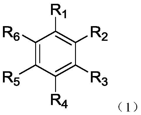
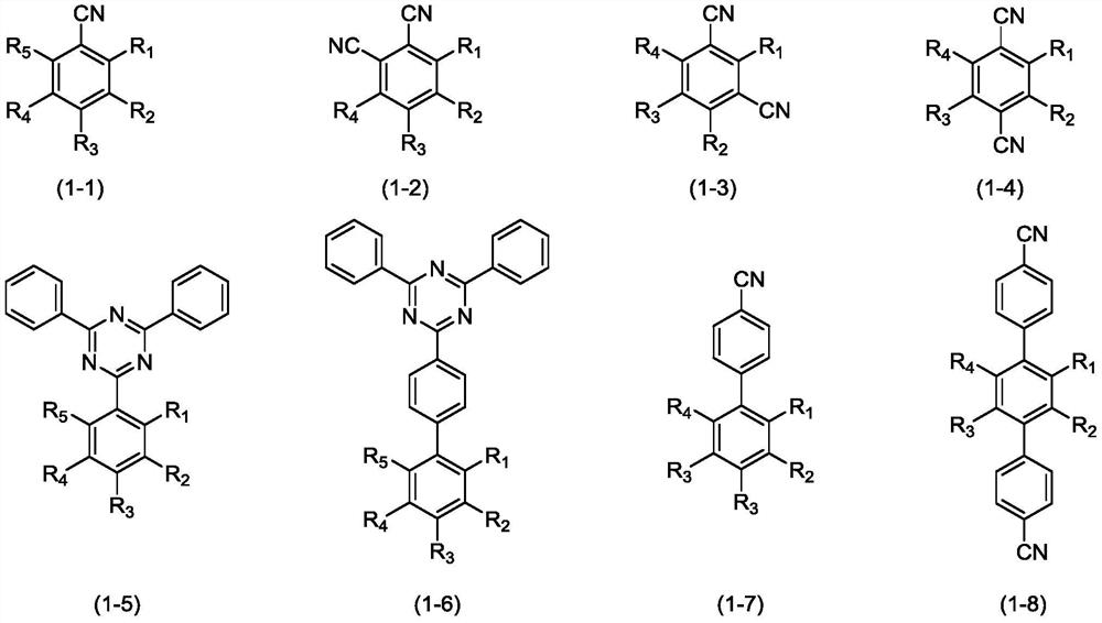
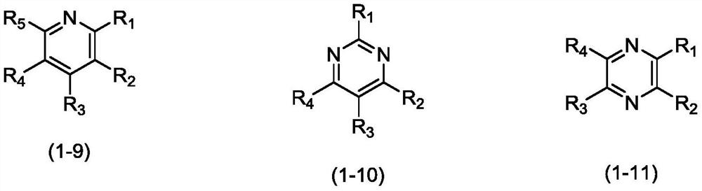
The invention relates to the technical field of organic electroluminescence, in particular to an organic compound, application thereof and an organic electroluminescence device containing the compound, and particularly relates to a novel thermal activation delayed fluorescence material. The material has the structure in the the formula (1), wherein R1-R6 is independently selected from cyano groups, deuterium atoms or one of perdeuterium-substituted groups selected from substituted or unsubstituted C3-C60 monocyclic heteroaryl containing at least one nitrogen atom, substituted or unsubstitutedC3-C60 fused ring heteroaryl containing at least one nitrogen atom, substituted or unsubstituted C6-C30 arylamino, and substituted or unsubstituted C3-C30 heteroarylamino groups, and at least one of R1-R6 is a cyano group. The compound disclosed by the invention has the advantages that when the compound is used as a luminescent layer material in an OLED device, the compound has better thermal stability, higher photoluminescencequantum efficiency and higher reverse intersystem jump rate, and can show excellent device efficiency and stability. The invention also discloses an organic light-emitting device adopting the compound with the general formula.
Description
technical field [0001] The invention relates to the technical field of organic electroluminescence, in particular to an organic compound and its application, and an organic electroluminescent device containing the compound, in particular to a thermally activated delayed fluorescent material. Background technique [0002] Organic electroluminescent devices (OLED: Organic Light Emission Diodes) are a type of device with a sandwich-like structure, including positive and negative electrode film layers and an organic functional material layer sandwiched between the electrode film layers. Apply voltage to the electrodes of the OLED device, positive charges are injected from the positive electrode, and negative charges are injected from the negative electrode. Under the action of the electric field, the positive and negative charges migrate in the organic layer and recombine to emit light. Due to the advantages of high brightness, fast response, wide viewing angle, simple process, ...
Claims
Application Information
Patent Timeline
Application Date:The date an application was filed.
Publication Date:The date a patent or application was officially published.
First Publication Date:The earliest publication date of a patent with the same application number.
Issue Date:Publication date of the patent grant document.
PCT Entry Date:The Entry date of PCT National Phase.
Estimated Expiry Date:The statutory expiry date of a patent right according to the Patent Law, and it is the longest term of protection that the patent right can achieve without the termination of the patent right due to other reasons(Term extension factor has been taken into account ).
Invalid Date:Actual expiry date is based on effective date or publication date of legal transaction data of invalid patent.

