
Installation device for long shaft of ventilating nozzle

A technology for installing devices and ventilating nozzles, which is applied in the direction of hand-held tools and manufacturing tools, can solve the problems of poor product quality, difficult to control the included angle, and high scrap rate, so as to reduce production costs, easy to control the included angle, and reduce the scrap rate Effect

Inactive Publication Date: 2016-06-01
JIANGSU HENGMINGDA AVIATION EQUIP CO LTD
View PDF6 Cites 0 Cited by
  • Summary
  • Abstract
  • Description
  • Claims
  • Application Information

AI Technical Summary

Problems solved by technology

Since the assembly between the long axis and the ventilation cover is completely manual, the angle between the long axis and the surface of the ventilation cover is difficult to control, and the product consistency is poor, resulting in poor product quality
And because the assembly between the long shaft and the ventilation cover is completely manual, it is difficult to control the depth of the lower end of the long shaft inserted into the ventilation cover. Although there is a lower boss in the center of the lower surface of the ventilation cover, the lower end of the long shaft will still pass through the ventilation during the assembly process. The situation of the cover makes the scrap rate higher, thus increasing the production cost

Method used


Image

  • Installation device for long shaft of ventilating nozzle
  • Installation device for long shaft of ventilating nozzle

Examples


Embodiment Construction

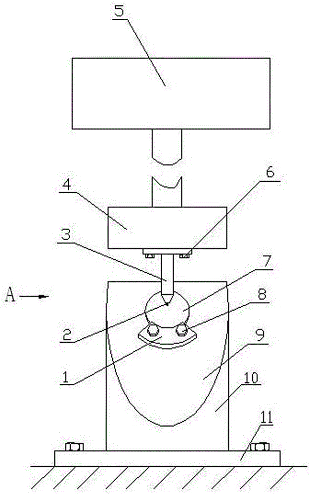
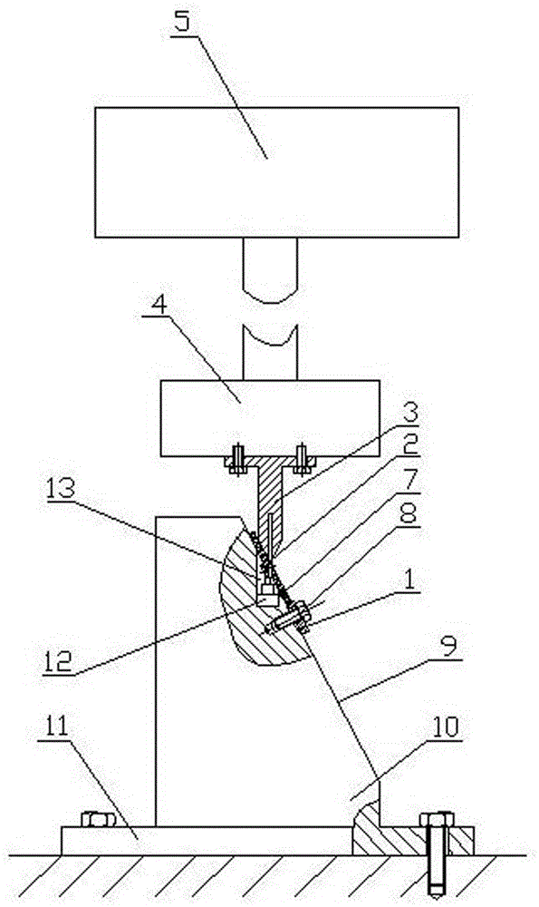
[0013] Such as figure 1 and figure 2 As shown, the installation device for the long axis of the air nozzle of the present invention includes a base 10, the base 10 is cylindrical, and a workbench 11 is fixed at its lower end. The upper side of the base 10 is processed with a beveled surface 9, and the beveled surface 9 is aligned with the vertical The included angle of the line is equal to the included angle between the long axis 2 of the ventilation nozzle and the cover surface of the ventilation cover 7 . An upper vertical blind hole 13 is processed on the beveled surface 9 , and a limit block 12 is fixed on the bottom of the upper vertical blind hole 13 . On the chamfered surface 9 below the opening of the upper vertical blind hole 13, a bracket 1 for supporting the ventilation cover 7 is arranged. An indenter 4 is arranged on the top of the base 10 , and a hydraulic press 5 is arranged above the indenter 4 . A push rod 3 is fixed below the pressure head 4 by means of a...


PUM


Abstract

The invention discloses an installation device for a long shaft of a ventilating nozzle. The installation device for the long shaft of the ventilating nozzle is characterized in that the installation device comprises a base; a diagonal plane is arranged on one side of the upper portion of the base, and the included angle between the diagonal plane and a vertical line is equal to the included angle between the long shaft of the ventilating nozzle and the cover surface of a ventilating cover of the ventilating nozzle. An upper vertical blind hole is formed in the diagonal plane. A limiting block is arranged at the hole bottom of the upper vertical blind hole. A supporting block used or supporting the ventilating cover is arranged on the portion, below the orifice of the upper vertical blind hole, of the diagonal plane. A pressing head is arranged at the top of the base. A hydraulic machine is arranged above the pressing head. An ejector rod is fixed below the pressing head. The diameter of the ejector rod is matched with that of the upper vertical blind hole. A lower vertical blind hole is formed in the center of the lower end of the ejector rod. The diameter of the lower vertical blind hole is matched with that of the installed long shaft. By assembling the long shaft and the ventilating cover through the installation device, the product quality can be improved, and the production cost is reduced. The installation device is suitable for assembly of the long shaft and the ventilating cover on the ventilating nozzle in a helicopter cabin.

Description

technical field [0001] The invention relates to a tool. Specifically, it is a long-axis installation device for installing the long axis on the vent cover of the ventilating nozzle, and is suitable for the assembly between the long axis and the venting cover on the ventilating nozzle in the helicopter cabin. Background technique [0002] All know in the field of helicopter manufacture, in order to keep the air in the cabin good, ventilating nozzles are all installed in the cabin of helicopter. The ventilation nozzle contains a ventilation cover for adjusting the air volume, and a long shaft is installed on the ventilation cover. One end of the long axis is tightly inserted and fixed in the center of the ventilation cover, and a large inclination angle is formed between the axial direction of the long axis and the cover surface of the ventilation cover. At present, the method of installing the long axis on the vent nozzle to the vent cover is manual operation, that is, one ...

Claims


Application Information

Patent Timeline
IPC IPC(8): B25B27/02
CPCB25B27/026
Inventor 刘凯钱承余
Owner JIANGSU HENGMINGDA AVIATION EQUIP CO LTD
Learn More