Uniform conveying device used for pin shaft parts

A technology for conveying devices and parts, applied in the field of uniform conveying devices, can solve the problems of increased error rate of item separation, limited human energy, and many people needed, and achieves high work efficiency, no movement noise, and the effect of solving plastic problems.

Inactive Publication Date: 2016-06-01
SHENGZHOU YIHAI MOTOR PARTS FACTORY
View PDF16 Cites 7 Cited by
  • Summary
  • Abstract
  • Description
  • Claims
  • Application Information

AI Technical Summary

Problems solved by technology

However, such a manual transportation method is cumbersome, requires more personnel, is time-consuming and labor-intensive, and human energy is limited after all. Long-term work will inevitably lead to poor ene

Method used


Image

  • Uniform conveying device used for pin shaft parts
  • Uniform conveying device used for pin shaft parts
  • Uniform conveying device used for pin shaft parts

Examples


Embodiment Construction

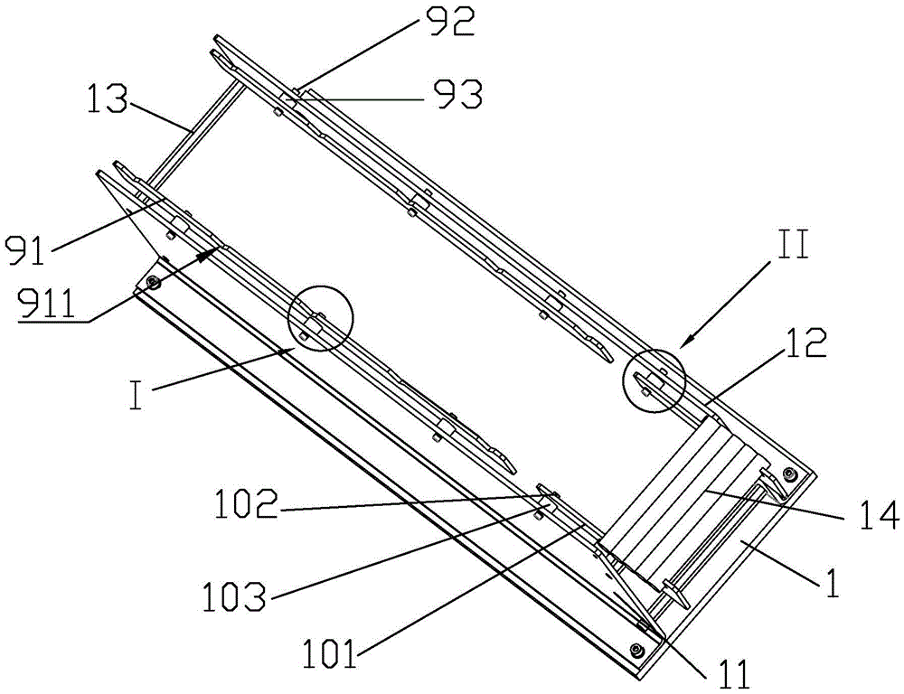
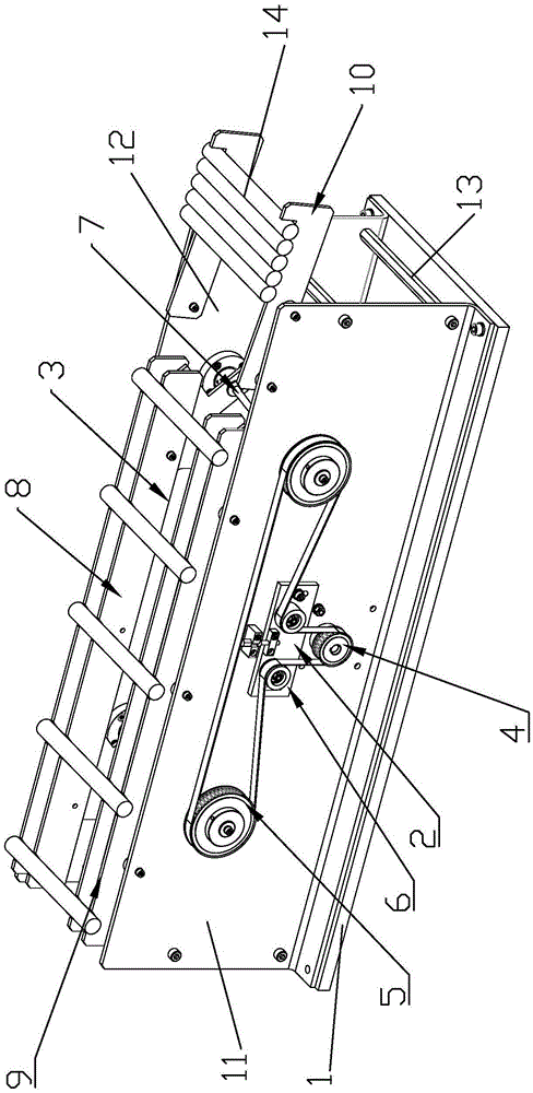
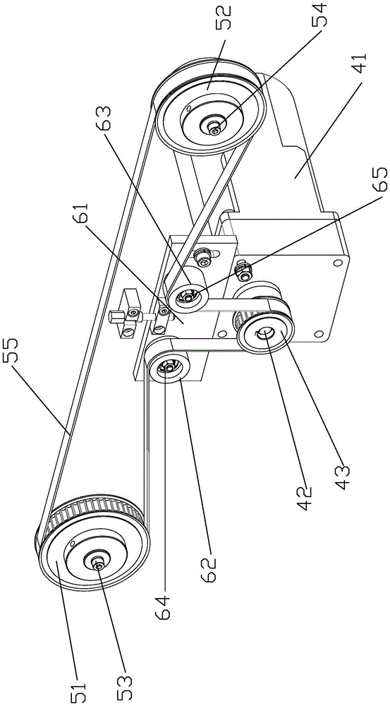
[0035] Such as Figure 1 to Figure 9 As shown, a uniform conveying device for pin shaft parts includes a conveying base 1, a conveying driving mechanism 2 and a conveying mechanism 3. The conveying base 1 is provided with a conveying driving mechanism 2, and the conveying driving mechanism 2 is connected to the conveying mechanism 3. The conveying base 1 is provided with a conveying rack, which includes a first conveying rack 11 and a second conveying rack 12. The first conveying rack 11 is installed on the front side of the conveying base 1, and the second conveying rack 12 is installed on the rear of the conveying base 1. side. A fixing rod 13 is provided between the first transfer rack 11 and the second transfer rack 12. By installing the fixing rod 13, the structure of the conveying driving mechanism 2 and the conveying mechanism 3 installed between the first conveying rack 11 and the second conveying rack 12 is stronger. A transmission driving mechanism 2 is provided on ...


PUM


Abstract

The invention discloses a uniform conveying device used for pin shaft parts. The uniform conveying device comprises a conveying base, a conveying drive mechanism and a conveying mechanism. The conveying base is provided with the conveying drive mechanism. The conveying drive mechanism is connected with the conveying mechanism. The conveying base is provided with a conveying frame which comprises a first conveying frame body and a second conveying frame body. The first conveying frame body is provided with the conveying drive mechanism, and the conveying mechanism is arranged between the first conveying frame body and the second conveying frame body. The conveying drive mechanism comprises a drive assembly, a guide wheel tensioning assembly, a belt transmission assembly and an eccentric transmission assembly. The drive assembly is connected with the belt transmission assembly. The belt transmission assembly is connected with the eccentric transmission assembly and the guide wheel tensioning assembly. The conveying mechanism comprises a conveying lifting assembly and a conveying moving assembly. The uniform conveying device can be used for conveying and machining of pin shaft parts and cylindrical workpieces and is very wide in application range, high in work efficiency, easy to operate and capable of greatly increasing the working efficiency and the finished product qualification rate.

Description

Technical field [0001] The invention relates to a uniform conveying device for pin shaft parts. Background technique [0002] In the existing machinery production, manufacturing, and processing lines, the separation of large quantities of pin and shaft workpieces is generally carried out by manipulators or manual conveying methods, and some use manipulator clamping methods, but such equipment is generally more expensive High, not suitable for small processing plants. For the manual conveying method, a pile of conveyed workpieces is manually placed on the workstation to be processed for the next step. However, such a manual conveying method is cumbersome, requires more personnel, is time-consuming and labor-intensive, and the human energy is limited after all. Long-term work will inevitably lead to poor spirits and increase the error rate of item separation. In today's era of high-precision and high-efficiency development, such a separation method will greatly reduce the profits...

Claims


Application Information

Patent Timeline
IPC IPC(8): B65G25/02
CPCB65G25/02B65G2201/0217
Inventor 陈意
Owner SHENGZHOU YIHAI MOTOR PARTS FACTORY
Why Eureka
Try Eureka