MEMS release auxiliary structure and preparation method thereof

A technology of auxiliary structure and structural layer, applied in the field of MEMS release auxiliary structure and its preparation, can solve the problems of diffraction effect, adverse effect on device performance, reduce device reflection coefficient, etc., achieve complete process compatibility, easy industrial value, and shorten the release length. Effect

Inactive Publication Date: 2016-06-01
苏州工业园区纳米产业技术研究院有限公司
View PDF6 Cites 6 Cited by
  • Summary
  • Abstract
  • Description
  • Claims
  • Application Information

AI Technical Summary

Problems solved by technology

[0003] However, these corrosion holes will more or less adversely affect the performance of the device. For example, the corrosion holes on the light reflector will not only reduce the reflection coefficient of the device, but also cause diffraction effects.

Method used


Image

  • MEMS release auxiliary structure and preparation method thereof
  • MEMS release auxiliary structure and preparation method thereof
  • MEMS release auxiliary structure and preparation method thereof

Examples


Embodiment 1

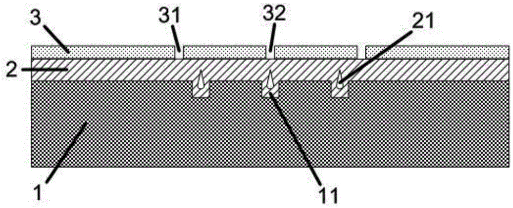
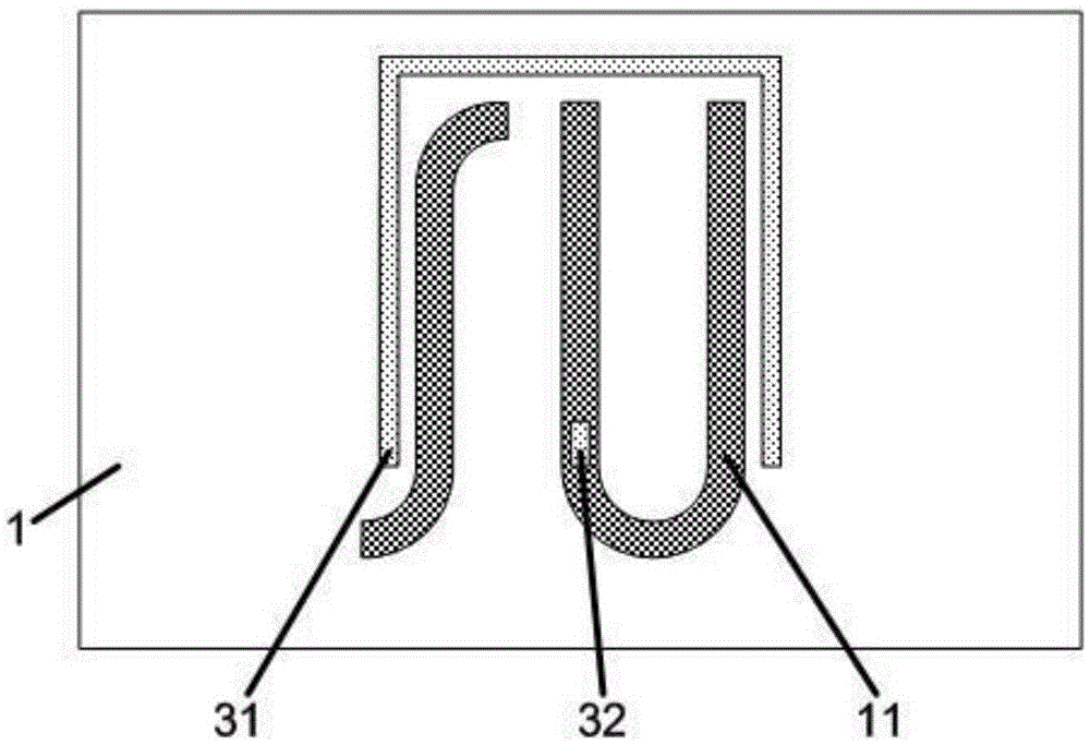
[0031] Such as Figure 1-2 , a MEMS release auxiliary structure, including a bottom layer, and a second sacrificial layer 2 and a second structural layer 3 arranged on the bottom layer in sequence, three grooves are arranged on the side of the bottom layer near the second sacrificial layer 2, and the second sacrificial layer 2 extend into the grooves, and form cavities 21 in each corresponding groove, and the air pressure in the cavities 21 is lower than the air pressure in the corrosive environment. Each of the etchant inlets is one of the etchant inlets, one of the etchant inlets is specifically the structural layer through-hole, and the other of the etchant inlet is specifically the release auxiliary hole 32. The through hole in the structural layer is more specifically the boundary opening 31 in this embodiment.

[0032] Here, the design of the release auxiliary hole 32 is an icing on the cake in terms of shortening the release length for devices with boundary openings 31...

Embodiment 2

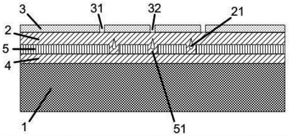
[0041] Such as image 3 , a MEMS release auxiliary structure, the difference from Embodiment 1 is that the bottom layer is formed by sequentially forming a first sacrificial layer 4 and a first structure layer 5 on a substrate 1 . The first sacrificial layer 4 is silicon oxide, and the first structural layer 5 is polysilicon.

[0042] The difference between the preparation method of the MEMS release auxiliary structure of this embodiment and the preparation method of Example 1 is:

[0043] Before step (1), first deposit silicon oxide on the substrate 1 to form the first sacrificial layer 4, then deposit polysilicon on the first sacrificial layer 4 to form the first structural layer 5, thereby forming the bottom layer, and in step (1) on the bottom layer The groove is specifically composed of a through hole 51 etched on the first structure layer 5 .

[0044] The working principle of the MEMS release auxiliary structure in this embodiment is the same as that in Embodiment 1. O...


PUM


Abstract

The invention relates to an MEMS release auxiliary structure and a preparation method thereof. The structure comprises a bottom layer, and a second sacrificial layer and a second structure layer successively arranged on the bottom layer; the side of the bottom layer close to the second sacrificial layer is equipped with a plurality of grooves; the second sacrificial layer extends to the grooves and respectively forms hollow cavities in corresponding grooves; the air pressures in the hollow cavities are less than the air pressure in a corrosive environment; a plurality of corrosive agent inlets for communicating the outside world and the second sacrificial layer are arranged on the second structure layer; at least one corrosive agent inlet is a structure layer through hole or a release auxiliary hole; and the bottom layer is an underlay or is prepared by successively forming a sacrificial layer and a first structure layer on the underlay. According to the MEMS release auxiliary structure provided by the invention, the corrosive agent corrodes the second sacrificial layer through the hollow cavities towards the periphery; the release length is effectively reduced; and the corrosive time is reduced.

Description

technical field [0001] The invention relates to a MEMS release auxiliary structure and a preparation method thereof. Background technique [0002] Since the 1990s, microelectromechanical systems (MEMS) technology has developed rapidly, and various MEMS devices such as accelerometers, silicon microphones, pressure sensors, gyroscopes, magnetic field sensors, and digital micromirrors have been successfully commercialized and gradually replaced similar traditional devices. , which means that the sensor has entered the era of MEMS. Among the MEMS processing methods, the release process is one of the most widely used processing technologies. At present, when the sacrificial layer is released, especially when the sacrificial layer is released with a large area, in order to shorten the release length and reduce the corrosion time, the usual practice is to design some corrosion holes on the structural layer in the release area, so that the liquid or gaseous etchant can pass along t...

Claims


Application Information

Patent Timeline
Patent Type & Authority Applications(China)
IPC IPC(8): B81B1/00B81C1/00
CPCB81B1/002B81C1/00047
Inventor 赵成龙张华
Owner 苏州工业园区纳米产业技术研究院有限公司
Why Eureka
Try Eureka