A computer-controlled ship anchor

A computer and anchor technology, applied in the field of computer-controlled anchors, can solve the problems of long distance between the hull and the anchor, dangers and hidden dangers of the hull, etc., and achieve the goal of preventing loose fixation, improving the degree of fixation, and improving grip Effect

Active Publication Date: 2021-02-26
江西数船科技有限公司
View PDF5 Cites 0 Cited by
  • Summary
  • Abstract
  • Description
  • Claims
  • Application Information

AI Technical Summary

Problems solved by technology

[0003] When the anchor in the prior art is used, the anchor is often hung on the reef of the seabed. However, in some places where the seabed is too flat and there are only mud layers, the anchor will not be able to fix the hull. When encountering waves and storms, the anchor cannot fix the hull, so that the hull is prone to safety hazards. At the same time, when anchoring, because the anchor drops slowly, the distance between the hull and the anchor is relatively long. When encountering During sea waves, the floating range of the hull body will increase, thereby reducing the fixing effect on the hull and easily causing danger to the hull

Method used


Image

  • A computer-controlled ship anchor
  • A computer-controlled ship anchor
  • A computer-controlled ship anchor

Examples


Embodiment 1

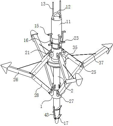
[0030] Example 1, such as Figure 1-Figure 7 As shown, a computer-controlled ship anchor according to the present invention includes an anchor body 1; the anchor body 1 includes a driving rod 11; a hanging ring 12 is fixedly connected to the inner wall of the driving rod 11 above the driving rod 11 A rope 13 is installed on the hanging ring 12, and the number of the rope 13 is two; a first motor 14 is installed in the inner wall of the drive rod 11, and the first motor 14 is connected with a computer signal through a controller; A connecting rod 2 is fixedly connected to the drive shaft of the motor 14; an auxiliary ring 21 is rotationally connected to the outer surface of the connecting rod 2 under the driving rod 11; the first support plate 15 evenly arranged is fixed on the outer surface of the driving rod 11; The inner wall of the auxiliary ring 21 is provided with uniformly arranged first chute 22, and a second support plate 23 is slidably connected in the first chute 22;...

Embodiment 2

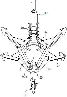
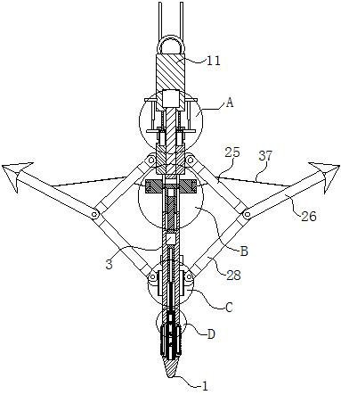
[0032] Embodiment 2 is different from Embodiment 1 in that a second motor 3 is fixedly connected to the inner wall of the connecting rod 2 below the auxiliary ring 21, and the second motor 3 is connected to the computer signal through the controller; the second motor 3 is a double-headed motor; the drive shaft above the second motor 3 is fixedly connected with a first lead screw 31; a second chute 32 is provided above the first lead screw 31, and slides in the second chute 32 A first jacking block 33 is connected; the first jacking block 33 is connected to the first lead screw 31 through threads; the outer side of the first jacking block 33 is provided with a third chute 34 evenly arranged in the inner wall of the connecting rod 2; The first jacking block 33 is fixedly connected with a support ring 35 through evenly arranged connecting rods, and the support ring 35 is slidably connected with the connecting rod 2;

[0033] When working, when the anchor body 1 is screwed into th...

Embodiment 3

[0034] Embodiment 3, different from Embodiment 2, is that a collar 36 is connected to the inner wall of the support ring 35 through ball rotation; the inner wall of the collar 36 is fixed with evenly arranged stay ropes 37, and the stay ropes 37 are all Made of metal material; the other end of each stay rope 37 passes through the first anchor rod 25 and is fixedly connected with the second anchor rod 26;

[0035] During work, because the collar 36 that is rotatably connected in the inner wall of the brace ring 35 is fixedly connected with the second anchor rod 26 by the stay cord 37, when the connecting rod 2 drives the brace ring 35 to rotate, the collar 36 will be in the brace ring 35. Rotation occurs, so as to prevent the stay rope 37 from being entangled with the first anchor rod 25. When the anchor body 1 needs to be retracted, the computer controls the second motor 3 to rotate clockwise. During the clockwise rotation of the second motor 3, it can Drive the first jacking ...


PUM


Abstract

The invention belongs to the technical field of ships, and is specifically a computer-controlled ship anchor; it includes an anchor body; the anchor body includes a driving rod; above the driving rod, a hanging ring is fixedly connected to the inner wall of the driving rod; A first motor is installed in the inner wall of the driving rod; a connecting rod is fixedly connected to the driving shaft of the first motor; an auxiliary ring is connected to the outer surface of the connecting rod below the driving rod; Some seabeds are too flat and there are only some places with mud layer. The anchor will not be able to fix the hull. When encountering waves and storms, the anchor cannot fix the hull, so that the hull is prone to safety hazards. At the same time, in When anchoring, because the anchor drops slowly, the distance between the hull and the anchor is relatively long. When encountering waves, the floating range of the hull body will increase, thereby reducing the fixing effect on the hull, and it is easy to make the hull Dangerous.

Description

technical field [0001] The invention belongs to the technical field of ships, in particular to a computer-based anchor. Background technique [0002] The anchor is the main part of the anchoring equipment. It is a kind of iron ship stopping device. It is connected to the ship with an iron chain, and the anchor can be dropped on the bottom of the water to make the ship stop. There are still some problems with the current anchor, specifically including the following aspects: [0003] When the anchor in the prior art is used, the anchor is often hung on the reef of the seabed. However, in some places where the seabed is too flat and there are only mud layers, the anchor will not be able to fix the hull. When encountering waves and storms, the anchor cannot fix the hull, so that the hull is prone to safety hazards. At the same time, when anchoring, because the anchor drops slowly, the distance between the hull and the anchor is relatively long. When encountering During sea wav...

Claims


Application Information

Patent Timeline
Patent Type & Authority Patents(China)
IPC IPC(8): B63B21/22B63B21/24
CPCB63B21/22B63B21/24
Inventor 贾荣芝张书明牛玫允丁建新周虹
Owner 江西数船科技有限公司
Why Eureka
Try Eureka