

Buckling floor
A floor and buckle technology, which is applied in the direction of floors, buildings, building structures, etc., can solve the problems of vertical installation, complicated processing technology, waste of materials, etc., to facilitate installation and maintenance, simplify processing technology, and reduce material waste Effect
- Summary
- Abstract
- Description
- Claims
- Application Information
AI Technical Summary
Problems solved by technology
Method used
Image

Examples
Embodiment 1
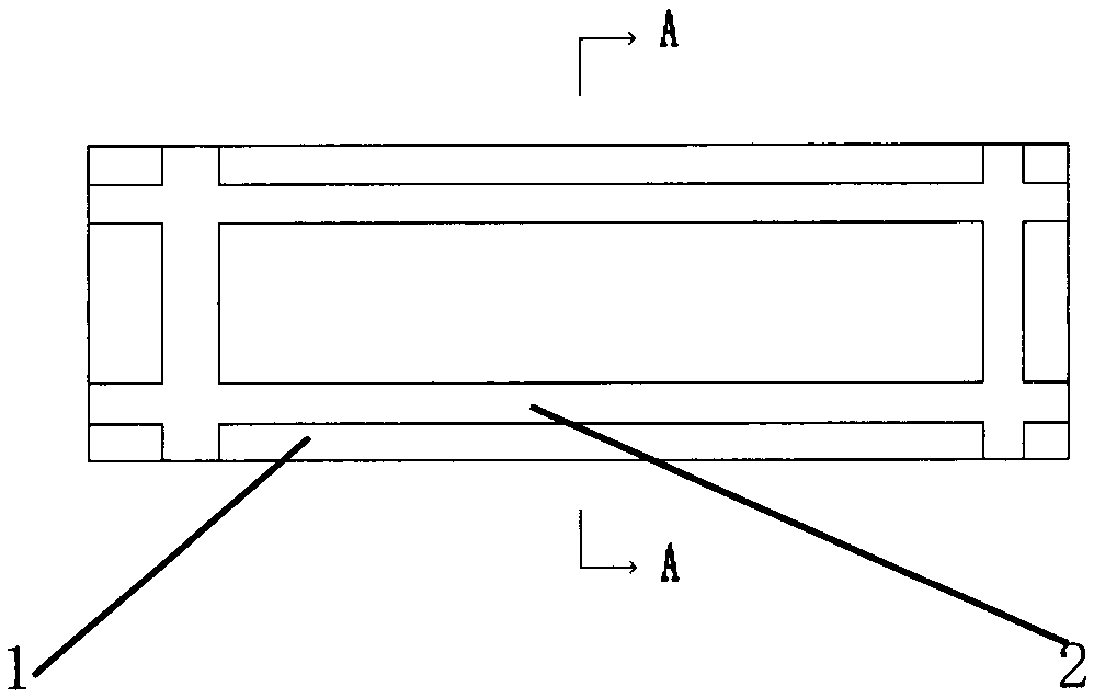
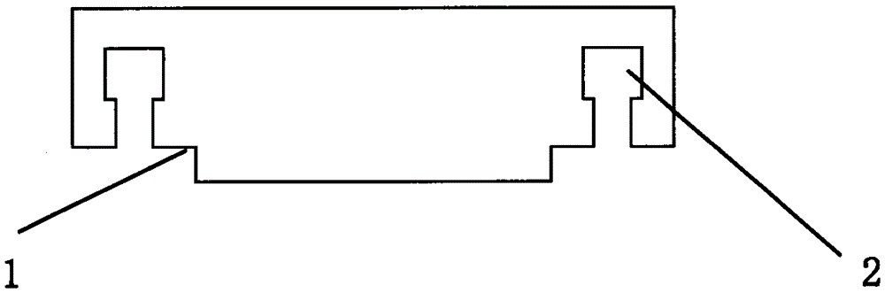
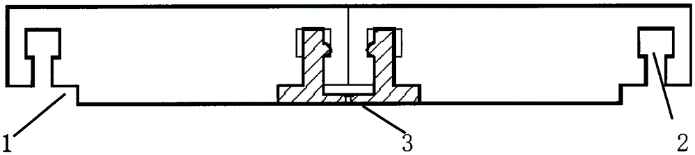
[0018] Embodiment 1: as figure 1 As shown in the structure diagram of the back of the buckle floor, there is a gap 1 and a buckle 2 on the back of the inner edge of the buckle floor. Such as figure 2 As shown in the cross-sectional diagram of the buckle floor, the buckle 2 is a T-shaped groove. Such as image 3 As shown in the schematic diagram of the buckle floor installation structure, the fastener 3 can be fixed on the ground or the wall by a solid piece such as a screw. The top of the clip spring of piece 3 can also be provided with a protrusion, which forms a concave-convex lock with the T-shaped groove of buckle 2, and plays a further fixing role; one side of fastener 3 is embedded in floor gap 1, which can ensure that the bottom surface of fastener 3 is in line with The back of the floor is on a plane to ensure the closeness between the back of the floor and the ground or the wall. The floor and the ground or the wall form a complete force-bearing surface, and the f...
Embodiment 2
[0020] Embodiment 2: as Figure 4 As shown in the cross-sectional diagram of the buckle floor, the buckle 2 is a T-shaped protrusion. Such as Figure 5 As shown in the schematic diagram of the buckle floor installation structure, the clip spring of fastener 3 is a T-shaped groove, and the clip spring of fastener 3 is inserted vertically into the buckle 2 of the floor. The T-shaped groove at the top forms a concave-convex lock with the T-shaped protrusion of the buckle 2, which plays a further role in fixing.
Embodiment 3
[0021] Embodiment 3: as Figure 5 As shown in the cross-sectional diagram of the buckle floor, the buckle 2 is a Y-shaped protrusion. Such as Figure 7 As shown in the schematic diagram of the buckle floor installation structure, the clip spring of fastener 3 is a T-shaped groove, and the clip spring of fastener 3 is inserted vertically into the buckle 2 of the floor. The T-shaped groove at the top forms a concave-convex lock with the Y-shaped protrusion of the buckle 2, which plays a further role in fixing.
PUM
 Abstract
Description
Claims
Application Information