Ball reducer

A technology of ball reducer and installation part, which is applied in the direction of friction transmission, belt/chain/gear, mechanical equipment, etc. It can solve the problems of low transmission efficiency and large loss, achieve small friction loss, small friction, and improve transmission efficiency Effect

Active Publication Date: 2016-06-01
佛山市力普鑫精密技术有限公司
View PDF6 Cites 3 Cited by
  • Summary
  • Abstract
  • Description
  • Claims
  • Application Information

AI Technical Summary

Problems solved by technology

[0003] Due to the relatively large friction force when the gears mesh in the traditional gear reducer, the loss during transmission is relatively large, and the transmission efficiency is low. Considering that a robot will use multiple reducers, and a complete production line often requires multiple Robots, in this way, will cause greater energy consumption

Method used


Image

  • Ball reducer
  • Ball reducer
  • Ball reducer

Examples


Embodiment Construction

[0029] In order to facilitate the understanding of those skilled in the art, the present invention will be further described below in conjunction with the embodiments and accompanying drawings, and the contents mentioned in the implementation modes are not intended to limit the present invention.

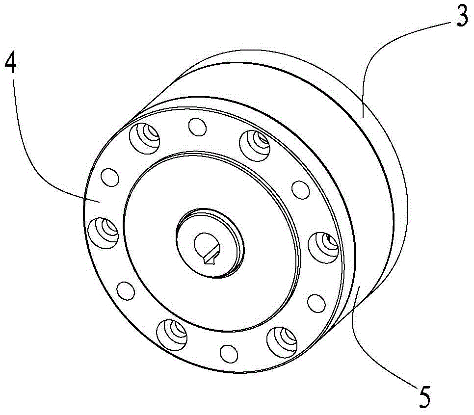
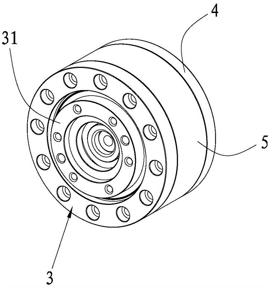
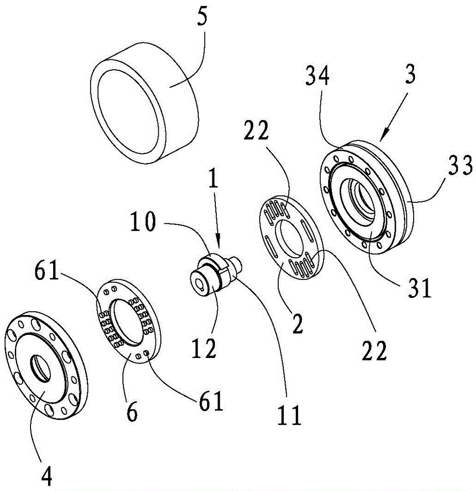
[0030] see figure 1 , figure 2 , image 3 , Figure 5 and Image 6 , the ball reducer of the present invention includes a shaft body 1, the shaft body 1 includes a mounting portion and an eccentric portion 10 connected to the mounting portion, the eccentric portion 10 is equipped with a drive disc 2, the mounting portion is equipped with an output disc 3, and the output disc 3. It includes an inner ring 31, an outer ring and a plurality of balls (not shown in the figure). The inner ring 31 is sleeved on the mounting part, the outer ring is sleeved on the inner ring 31, and multiple balls are installed Between the rings, the side of the driving disc 2 close to the inner ring 31 ...


PUM


Abstract

The invention relates to the technical field of reducers, and particularly discloses a ball reducer. The ball reducer comprises a shaft body. The shaft body comprises a mounting part and an eccentric part connected with the mounting part. The eccentric part is provided with a drive disc. The mounting part is provided with an output disc. The output disc comprises an inner ring, an outer ring and a plurality of balls. The mounting part is sleeved with the inner ring. The inner ring is sleeved with the outer ring. The multiple balls are arranged between the inner ring and the outer ring. A hypocycloid ring groove is formed in the side, close to the inner ring, of the drive disc. An epicycloid ring groove is formed in the side, close to the drive disc, of the inner ring. A plurality of roll balls are arranged between the hypocycloid ring groove and the epicycloid ring groove. During actual application, the shaft body of the ball reducer is connected with a motor, the inner ring serves as an output shaft, movement is transferred through rolling of the roll balls, and speed reduction on the motor is achieved; and rolling friction during rolling of the roll balls is smaller than friction during engagement of gears in a traditional gear reducer, the loss is small, and the transmission efficiency is greatly improved.

Description

technical field [0001] The invention relates to the technical field of reducers, and in particular discloses a ball reducer. Background technique [0002] Reducers are used in most mechanical production equipment. Traditional reducers use gear meshing to achieve deceleration. With the advancement of industrial modernization technology, more and more products have realized automated production. In the automated production process , It is necessary to use robots to replace the original manual operations, and each robot needs to use multiple reducers. [0003] Due to the relatively large friction force when the gears mesh in the traditional gear reducer, the loss during transmission is relatively large, and the transmission efficiency is low. Considering that a robot will use multiple reducers, and a complete production line often requires multiple Robots, like this, will cause greater energy consumption. Contents of the invention [0004] In order to overcome the shortcomi...

Claims


Application Information

Patent Timeline
Patent Type & Authority Applications(China)
IPC IPC(8): F16H13/04
CPCF16H13/04
Inventor 王小三
Owner 佛山市力普鑫精密技术有限公司
Why Eureka
Try Eureka