Same-floor rotational flow tee joint

A technology of three-way and three-way pipes, which is applied in the field of three-way pipes, can solve the problems of small bathroom headroom, heavy backfilling workload, and increased building load, etc., and achieve the effects of good ventilation capacity, improved drainage capacity, and reduced energy consumption

Active Publication Date: 2016-06-01
SHANGHAI SHANGSU HLDG GRP
View PDF6 Cites 1 Cited by
  • Summary
  • Abstract
  • Description
  • Claims
  • Application Information

AI Technical Summary

Problems solved by technology

[0004] The structure ring beam around the current tee pipe is large, the waterproof area is large, and the workload of backfilling is large. Yes, the headroom of the bathroom is small, which increases the load of the building, and the water in the water seal will be pumped under the siphon effect.

Method used


Image

  • Same-floor rotational flow tee joint
  • Same-floor rotational flow tee joint
  • Same-floor rotational flow tee joint

Examples


Embodiment

[0028] The same-level combiner in this embodiment is connected to the standpipe.

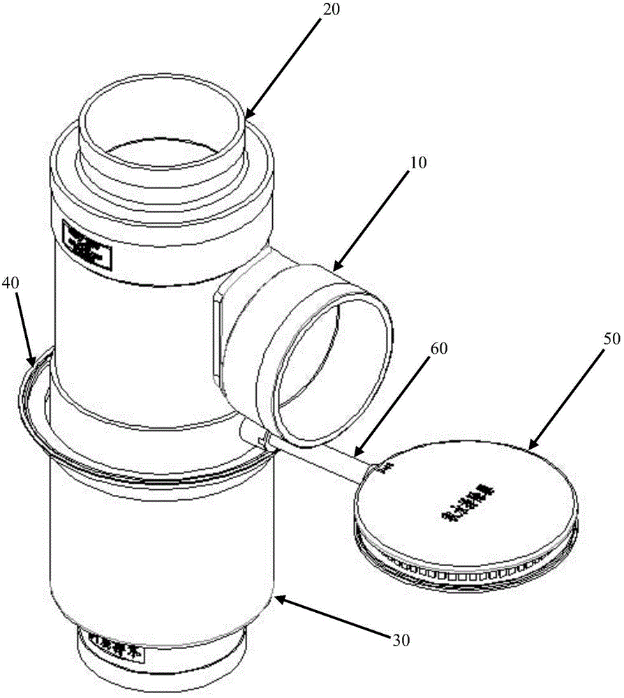
[0029] figure 1 It is a structural schematic diagram of the same-layer swirl tee in the embodiment of the present invention.

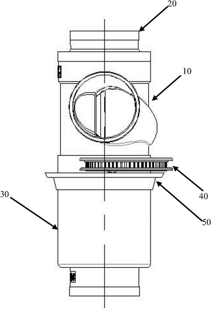
[0030] figure 2 It is the front view of the same-level swirl tee in the embodiment of the present invention.

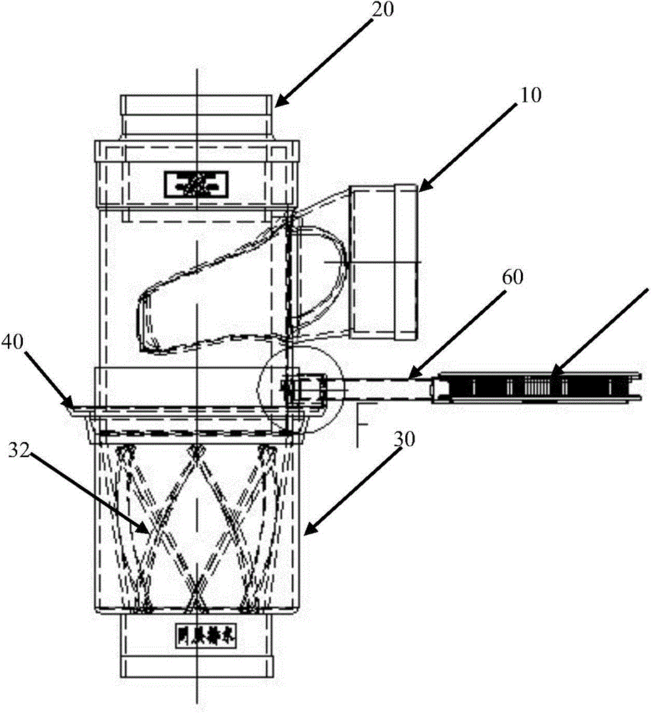
[0031] image 3 It is a full-section left view of the same-layer swirl tee in the embodiment of the present invention.

[0032] Figure 4 It is the top view of the same-layer swirl tee in the embodiment of the present invention.

[0033] Figure 5 It is an exploded schematic view of the same-layer swirl tee in the embodiment of the present invention.

[0034] Such as figure 1 , figure 2 , image 3 , Figure 4 , Figure 5 As shown, the swirl tee on the same floor includes: a tee main body 10 , a connecting cover 20 , a connecting pipe 30 , a round sleeve 40 , a drainer 50 and a connecting pipe 60 .

[0035] The three ends of the three-way pipe main...


PUM


Abstract

The invention provides a same-floor rotational flow tee joint which is connected with a vertical pipe. The same-floor rotational flow tee joint is characterized by comprising a tee pipe body, a connection cover, a connection pipe and a round sleeve, wherein the three ends of the tee pipe body are provided with a spigot and two sockets; the connection cover is mounted at any one of the two sockets of the tee pipe body while the other socket is sleeved with the connection pipe; the round sleeve is mounted in the connection position of the tee pipe body and the connection pipe in a sleeving mode so as to fix the connection pipe; a rotational flow guide water inlet is formed in the inner side of the connection pipe.

Description

technical field [0001] The invention relates to a tee pipe, in particular to a same-layer swirl tee with a swirl guide water inlet inside the pipe. Background technique [0002] The tee has three open fittings. Tee pipes are widely used in pipe networks for conveying liquids and gases. Due to the different conveying media, the material of the tee pipe is divided into: cast iron, cast steel, cast copper, cast aluminum, plastic, glass, etc. [0003] The metal tee has a main pipe and a branch pipe that is perpendicular to the main pipe and communicates with the main pipe on one side of the main pipe. A valve is installed at the corner where the outlet direction of the main pipe and the outlet direction of the branch pipe meet. The state is a structure that is mutually sealed with the inner wall of the lumen. The invention simplifies the arrangement of pipelines, saves the amount of pipeline components, facilitates operation, and is convenient for maintenance of pipeline bran...

Claims


Application Information

Patent Timeline
Patent Type & Authority Applications(China)
IPC IPC(8): F16L41/02F16L55/045F16L55/02
Inventor 潘心争俞良
Owner SHANGHAI SHANGSU HLDG GRP
Why Eureka
Try Eureka