Gas pipeline leak plugging device and method

A technology for gas pipelines and plugging methods, which is applied to pipe components, pipes/pipe joints/fittings, mechanical equipment, etc., and can solve problems such as potential safety hazards, threats to personnel life safety, unfavorable equipment safe operation, etc., and achieve simple and applicable steps strong effect

Active Publication Date: 2018-02-16
SHAANXI HUAFU NEW ENERGY
View PDF5 Cites 0 Cited by
  • Summary
  • Abstract
  • Description
  • Claims
  • Application Information

AI Technical Summary

Problems solved by technology

However, each plugging method has its own limitations and applicable conditions. If the method is not adopted properly, it will cause safety hazards, which is not conducive to the safe operation of equipment and threatens the safety of personnel.

Method used


Image

  • Gas pipeline leak plugging device and method
  • Gas pipeline leak plugging device and method
  • Gas pipeline leak plugging device and method

Examples


Embodiment Construction

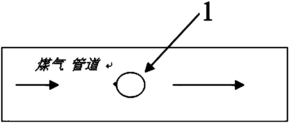
[0021] combine Figure 1-Figure 5 The technical scheme of the present invention is described:

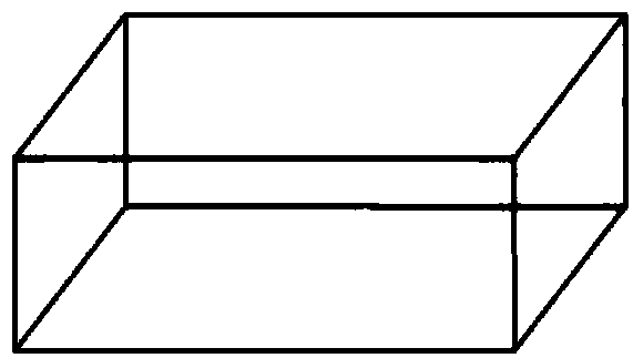
[0022] (1) To make a rectangular lead block box, make use of the low melting point and good ductility of the lead block to make a rectangular lead block box, and melt the lead block into the rectangular lead block box to make a rectangular lead plate.

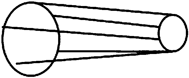
[0023] (2) According to the shape of the leak point of the gas pipeline, cut the rectangular lead plate obtained in step (1) into a small cuboid slightly larger than the shape of the leak point with a bow saw, and then smash it into the required shape with a hammer. Smashing into a round rod shape has less resistance and is easier to enter. Then use a copper chisel to chisel the round lead rod at the front to the required size, and align the round lead rod with the leak point of the gas pipe and smash it with a copper hammer. enter.

[0024] (3) Make a rectangular steel box, and fill the box with yellow mud. Then drill a hole at o...


PUM


Abstract

The invention discloses a device and a method for stopping leakage of a gas pipeline. Firstly, a lead piece is used for stopping leakage of a leaking part; for further preventing gas leakage, a steel box full of yellow mud is used for welding leaking positions, so that leaking points of the gas pipeline can be completely prevented from leakage. The leakage stoppage method is simple in steps, safe, reliable, high in applicability and applicable to leakage stoppage of gas systems and air pipes.

Description

technical field [0001] The invention relates to a pipeline leakage plugging device and method, in particular to a gas pipeline leakage plugging device and method. Background technique [0002] In a gas power plant, because the gas contains acidic media, it is easy to cause gas pipeline leakage. In practical applications, when plugging gas pipeline leakage, various plugging methods are generally used according to working conditions, processing capabilities, and site conditions ( There are mechanical plugging method, plug hole plugging method, welding repair plugging method, adhesive plugging method, glue plugging sealing method, replacement sealing method, etc.) combined for plugging, such as: plugging wedges first, then bonding, Finally, it is mechanically fixed (welding the fixing frame first, then using sealant, and finally mechanically pressing) and other methods. However, each plugging method has its own limitations and applicable conditions. If the method is not adopte...

Claims


Application Information

Patent Timeline
Patent Type & Authority Patents(China)
IPC IPC(8): F16L55/168
CPCF16L55/168
Inventor 闫军平石军生刘涛梁新民郭贵亭相里军旗韩小伟王东明孟航王若羲
Owner SHAANXI HUAFU NEW ENERGY
Why Eureka
Try Eureka