LED arched lens with long and narrow light spot

A technology of LED lamp beads and lenses, applied in the field of lenses, can solve the problems of increasing the volume and weight of lamps, large lens volume, and wide spot width, etc., and achieve the effect of simple structure, small volume, and concentrated light

Active Publication Date: 2016-06-01
东莞市鑫叶光学有限公司
View PDF8 Cites 9 Cited by
  • Summary
  • Abstract
  • Description
  • Claims
  • Application Information

AI Technical Summary

Problems solved by technology

The rectangular spot lens in the prior art, in some occasions, the spot width is too wide, and the length is not enough, such as window sill lamps, wall washers, etc.
At present, there are optical lens patents capable of producing rectangular light spots, such as the Chinese patent application with the application number 200820095648.1 titled "Slot Structure Secondary Optical Lens for Producing Rectangular Spots"; The Chinese patent application for the spotlight"; the application number is 201410414480.6, the Chinese patent application title is "collimator optical device for lamps"; the application number is 201520380096.9, the title is "a small optical angle strip lens integrated LED lamp "The Chinese patent application and other patent documents that can produce rectangular light spots are all elongated groove-shaped or rod-shaped lenses. The lens is bulky, which increases the volume and weight of the lamp, and the cost is high.

Method used


Image

  • LED arched lens with long and narrow light spot
  • LED arched lens with long and narrow light spot
  • LED arched lens with long and narrow light spot

Examples


Embodiment Construction

[0025] The present invention and its beneficial effects will be described in further detail below with reference to the examples, but the embodiments of the present invention are not limited thereto.

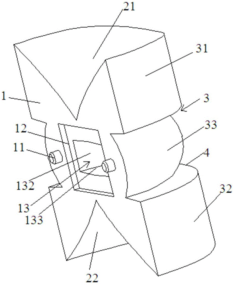
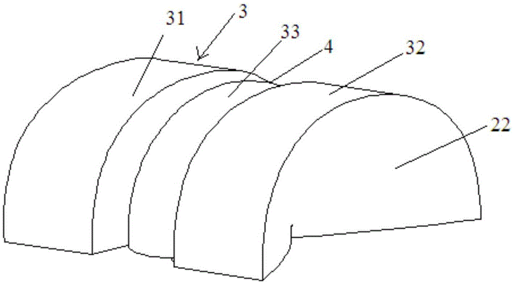
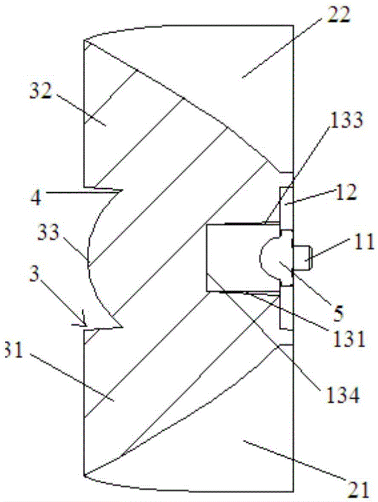
[0026] like Figure 1 to Figure 6 As shown in the figure, the present invention provides an LED arched lens with a narrow and long light spot. The lens includes LED lamp beads 5 and a concave incident hole 13 formed in the center of the bottom 1 of the lens, and a first hole formed on both sides of the lens. The reflecting surface 21 and the second reflecting surface 22, and the first arched portion 31, the second arched portion 32 and the third arched portion 33 formed on the top 3 of the lens, and the third arched portion 33 is formed on the first arched portion 33. Between the raised portion 31 and the second arched portion 32, the LED lamp bead 5 is located in the center of the incident hole 13, and the bottom of the LED lamp bead 5 is flush with the bottom edge of the incid...


PUM


Abstract

The invention belongs to the technical field of lenses, and particularly relates to an LED arched lens with a long and narrow light spot. The lens comprises an LED lamp bead, an incident hole formed in the bottom of the lens, a first reflecting face, a second reflecting face, a first arched part, a second arched part and a third arched part. The first reflecting face and the second reflecting face are formed on the two sides of the lens. The first arched part, the second arched part and the third arched part are formed on the top of the lens. The third arched part is formed between the first arched part and the second arched part. The LED lamp bead is located in the incident hole. Compared with the prior art, the total internal reflection theory and a free-form surface are combined, and light emitted by an LED lamp can be emitted out in a collimation manner in the width direction of the lens. The arched structure and the free-form surface are combined, and the light emitted by the LED lamp can be emitted to a place with a larger angle in the length direction of the lens. Therefore, the LED arched lens has the beneficial effects of being centralized in light condensation, small in light loss, simple in structure, small in size and the like, and the narrower and longer light spot can be generated.

Description

technical field [0001] The invention belongs to the technical field of lenses, and in particular relates to an LED arch lens with narrow and long light spots. Background technique [0002] LED lamps are used more and more widely, and for many industries, LED lenses are required to have special light types, high light yield and high brightness. For the rectangular light spot lens in the prior art, the light spot width is too wide and the length is insufficient in some occasions, such as window sill lamps, wall washer lamps and so on. At present, there are optical lens patents that can generate rectangular light spots, such as the Chinese patent application with the application number of 200820095648.1 and the title of "Secondary Optical Lens with Groove Structure for Generating Rectangular Light Spots"; The Chinese patent application of "Spotlight"; the Chinese patent application with the application number of 201410414480.6 and the title of "collimator optical device for la...

Claims


Application Information

Patent Timeline
Patent Type & Authority Applications(China)
IPC IPC(8): F21V5/04F21K9/69F21V19/00F21V31/00F21V17/00F21Y115/10
CPCF21V5/04F21V17/00F21V19/001F21V31/00
Inventor 韩敏叶正南
Owner 东莞市鑫叶光学有限公司
Why Eureka
Try Eureka