A multi-line optical fiber thermal stripper

A stripper and optical fiber technology, applied in the direction of light guides, optics, instruments, etc., can solve the problems of easily damaged fibers, low work efficiency, and excessive operation actions, so as to improve work efficiency, ensure stripping quality, and work intensity Reduced effect

Active Publication Date: 2018-08-31
WANMA TECH CO LTD
View PDF5 Cites 0 Cited by
  • Summary
  • Abstract
  • Description
  • Claims
  • Application Information

AI Technical Summary

Problems solved by technology

Most of the existing operation methods use scissor-type shearing tool to strip the sheath first, and then strip the coating layer. Each optical fiber needs to be operated twice, which is not only easy to damage the fiber, but also has too many operations and low work efficiency. high

Method used


Image

  • A multi-line optical fiber thermal stripper
  • A multi-line optical fiber thermal stripper
  • A multi-line optical fiber thermal stripper

Examples


Embodiment Construction

[0023] The present invention will be further described below in conjunction with the accompanying drawings, but the present invention is not limited to the following examples.

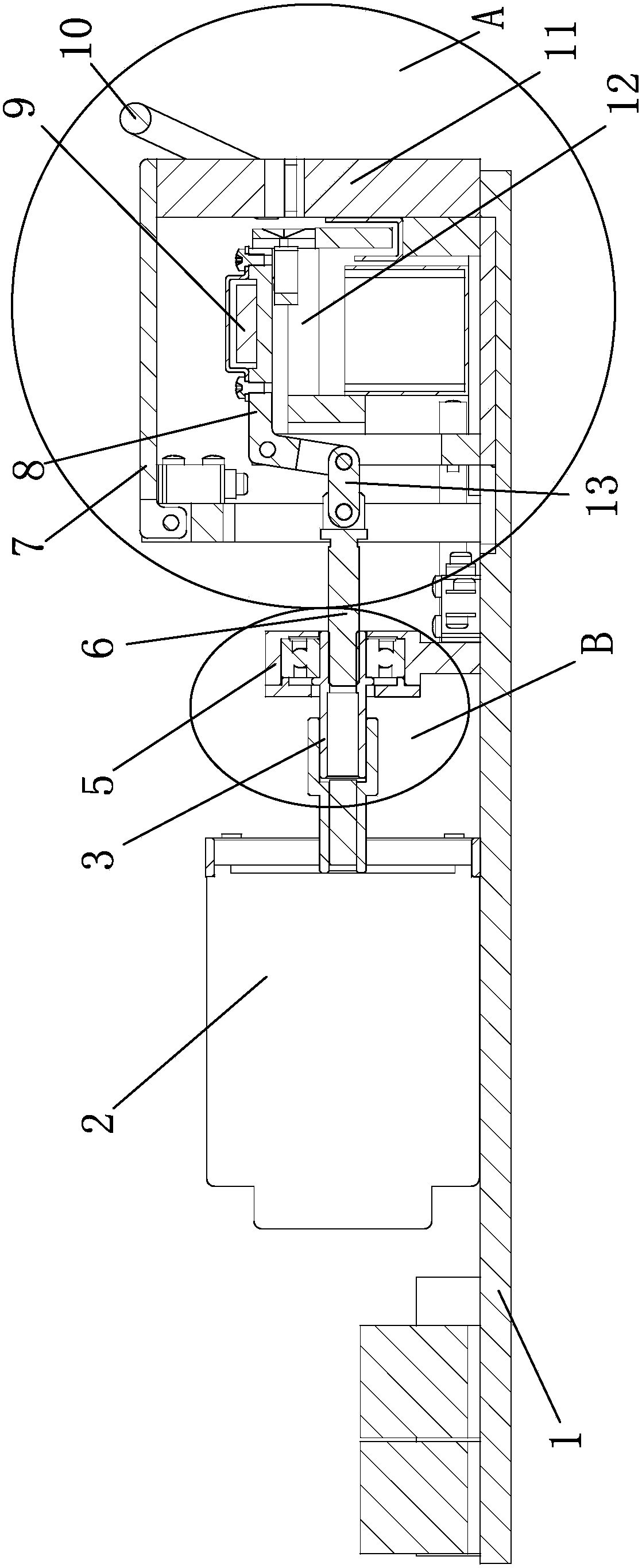
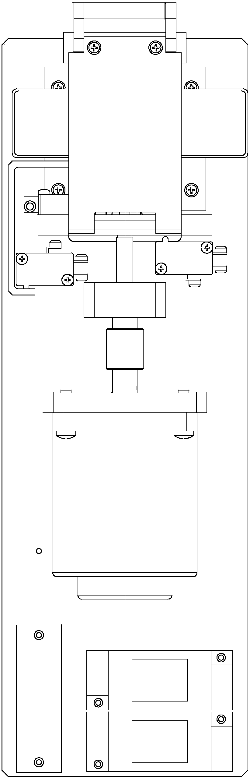
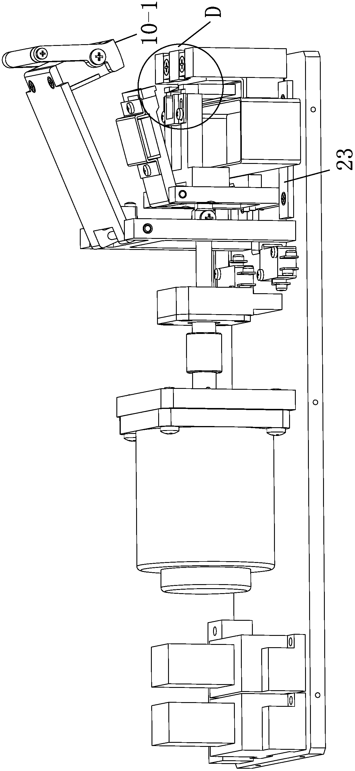
[0024] In the multi-core optical fiber stripper as shown in the figure, the clamping frame for clamping the optical cable is fixed on the base body 1, the cutter frame and the heater for heating the optical fiber are positioned in the clamping frame, and the power mechanism is used to drag The movement of the movable cutter holder.

[0025] The clamping frame is rotatably hinged as a whole by the upper pressing plate 7 and the lower pressing plate 11, and the middle parts of the upper and lower pressing plates are respectively equipped with rubber pads 24 (the view of the rubber pad of the upper pressing plate is omitted), thus forming a meshing mouth. It is used to clamp and fix the optical fiber so that it does not move during the stripping operation; magnets 20 are installed on both sides of the eng...


PUM


Abstract

The present invention relates to a multi-thread fiber heat stripper. The objective of the invention is to provide characteristics of simple structure, high work efficiency and easy and fast usage for the multi-thread fiber heat stripper. The multi-thread fiber heat stripper is characterized in that: the stripper comprises a base body, a clamping and pressing frame fixed on the base body and configured to clamp optical cables, a cutting knife rest located in the clamping and pressing frame, a heater configured to heat the fiber and a power mechanism configured to draw the cutting knife rest to move.

Description

technical field [0001] The invention relates to an optical fiber stripping device, in particular to a multi-line optical fiber thermal stripper. Background technique [0002] In the process of connector production or splicing of communication optical fibers, the outer sheath and the inner coating layer need to be stripped first. Most of the existing operation methods use scissor-type shearing tool to strip the sheath first, and then strip the coating layer. Each optical fiber needs to be operated twice, which is not only easy to damage the fiber, but also has too many operations and low work efficiency. high. Contents of the invention [0003] The purpose of the present invention is to overcome the shortcomings in the above-mentioned background technology and provide a multi-line optical fiber thermal stripper, which has the characteristics of simple structure, high working efficiency, and convenient and quick use. [0004] The technical solution of the present invention...

Claims


Application Information

Patent Timeline
Patent Type & Authority Patents(China)
IPC IPC(8): G02B6/245
CPCG02B6/245
Inventor 徐长鑫陈君兰吴佳
Owner WANMA TECH CO LTD
Why Eureka
Try Eureka