
Manufacturing method of color filter substrate

A technology for a color filter substrate and a manufacturing method, which are applied in the field of display panel manufacturing to achieve the effects of improving yield, avoiding poor concave and convex points, and preventing surface concave and convex points

Inactive Publication Date: 2016-06-01
WUHAN CHINA STAR OPTOELECTRONICS TECH CO LTD
View PDF10 Cites 0 Cited by
  • Summary
  • Abstract
  • Description
  • Claims
  • Application Information

AI Technical Summary

Problems solved by technology

[0005] Generally speaking, grinding can be used for poor Dimple, but the disadvantage of using grinding is that it increases the risk of grinding bright spots and insufficient stress (Fail), especially for large-size screens with relatively high stress requirements (such as 8.6 inches) , 10.1 inches, etc.)

Method used


Image

  • Manufacturing method of color filter substrate
  • Manufacturing method of color filter substrate
  • Manufacturing method of color filter substrate

Examples


Embodiment Construction

[0029] In order to further illustrate the technical means and effects adopted by the present invention, the following describes in detail in conjunction with preferred embodiments of the present invention and accompanying drawings.

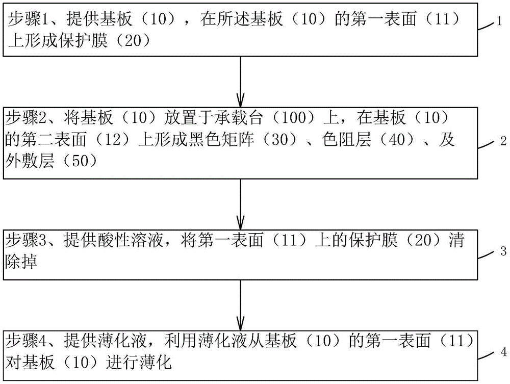
[0030] see figure 1 , the present invention provides a method for manufacturing a color filter substrate, comprising the following steps:

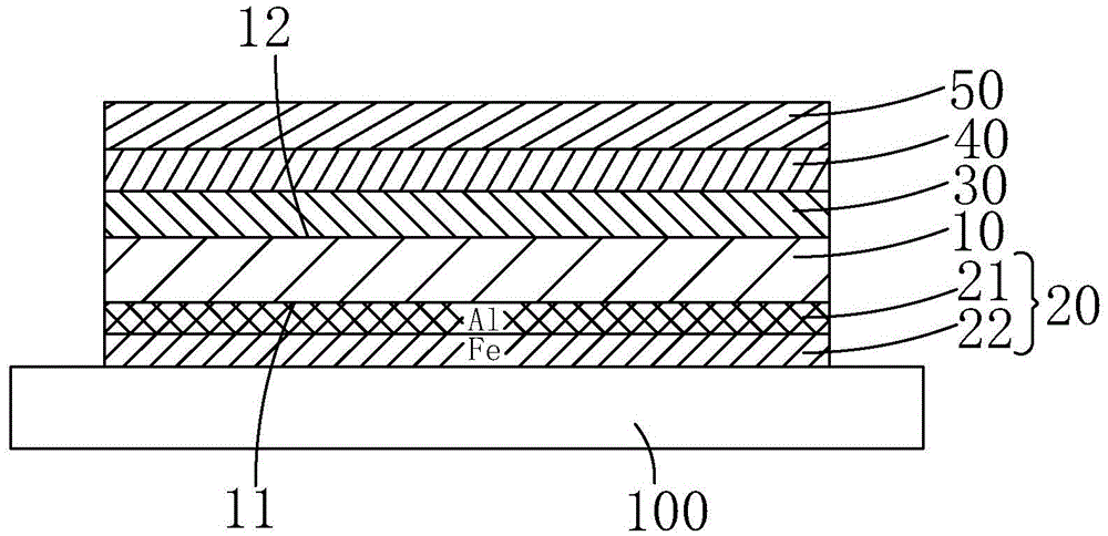
[0031] Step 1, such as figure 2 As shown, a substrate 10 is provided, and the two surfaces on opposite sides of the substrate 10 are set to be a first surface 11 and a second surface 12 respectively, and metal is deposited on the first surface 11 of the substrate 10 by a physical vapor deposition process. a protective film of material 20;

[0032] Specifically, the substrate 10 is a glass substrate.

[0033] Specifically, the protective film 20 has a double-layer structure, including a first protective layer 21 and a second protective layer 22 sequentially formed on the first surface 11 .

[0034] Prefera...


PUM


Abstract

The invention provides a manufacturing method of a color filter substrate. The manufacturing method of the color filter substrate comprises the following steps of first, depositing a protective film of a metal material on a surface of an incoming substrate, and then enabling the surface, on which the protective film is formed, on the substrate to be in contact with a bearing platform in a subsequent manufacturing process, forming a black matrix, a color resistive layer, an outer coating layer and the like on another surface of the substrate, afterwards, removing the protective film on the surface of the substrate by using an acid solution of hydrochloric acid and the like before the substrate is thinned, finally, thinning the substrate, and completing the manufacturing of the color filter substrate, so as to obtain the color filter substrate. The protective film can effectively protect the surfaces of the substrate, and prevents devices from causing damage to the surfaces of the substrate to result in the generation of concave and convex points on the surface in a manufacturing process, thereby avoiding the further aggravation of the poorness of the concave and convex points when the substrate is thinned; the yield of display panels is promoted.

Description

technical field [0001] The invention relates to the field of manufacturing display panels, in particular to a method for manufacturing a color filter substrate. Background technique [0002] A liquid crystal display device (LCD, Liquid Crystal Display) has many advantages such as a thin body, power saving, and no radiation, and has been widely used. Most of the liquid crystal display devices currently on the market are backlight liquid crystal display devices, which include a liquid crystal display panel and a backlight module. Usually, the liquid crystal display panel consists of a color filter substrate (CFSubstrate, ColorFilterSubstrate), a thin film transistor array substrate (TFTArray Substrate, ThinFilmTransistorArraySubstrate), a liquid crystal (LC, LiquidCrystal) sandwiched between the color filter substrate and the thin film transistor array substrate, and a sealant (Sealant) Composition; its molding process generally includes: front-end array (Array) process (thin...

Claims


Application Information

Patent Timeline
Patent Type & Authority Applications(China)
IPC IPC(8): G02F1/1335
CPCG02F1/133516G02F1/133519
Inventor 赵国涛
Owner WUHAN CHINA STAR OPTOELECTRONICS TECH CO LTD
Learn More