Auxiliary mechanism of the operating mechanism

An operating mechanism and auxiliary mechanism technology, which is applied to the protection switch operation/release mechanism, contact drive mechanism, switch equipment status indication, etc. effect of connection

Active Publication Date: 2018-10-30
SEARI ELECTRIC TECH +1
View PDF4 Cites 0 Cited by
  • Summary
  • Abstract
  • Description
  • Claims
  • Application Information

AI Technical Summary

Problems solved by technology

The existing structure is to realize the function in the form of an accessory, but cannot directly use the operating mechanism to achieve the function through linkage with it

Method used


Image

  • Auxiliary mechanism of the operating mechanism
  • Auxiliary mechanism of the operating mechanism
  • Auxiliary mechanism of the operating mechanism

Examples


Embodiment Construction

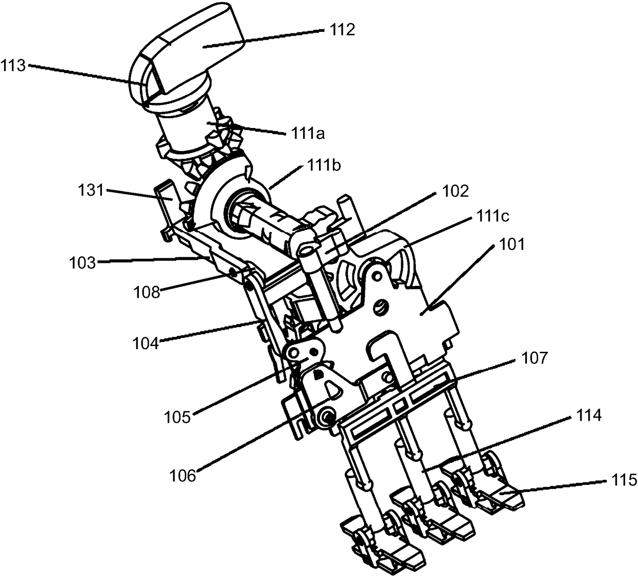
[0024] refer to figure 1 as shown, figure 1 A structural diagram of an auxiliary mechanism of an operating mechanism according to an embodiment of the present invention is disclosed. The auxiliary mechanism of the operating mechanism includes: transmission rod 102, first push rod 103, second push rod 104, rotating member 105, lever 106, pull rod 107, U-shaped rod 108, slider 109, lock catch 110, cam assembly 111a -111c, rotating handle 112, handle pulling block 113. The above-mentioned components cooperate with the operating mechanism main body 101 , the contact support assembly 114 and the contact bridge 115 .

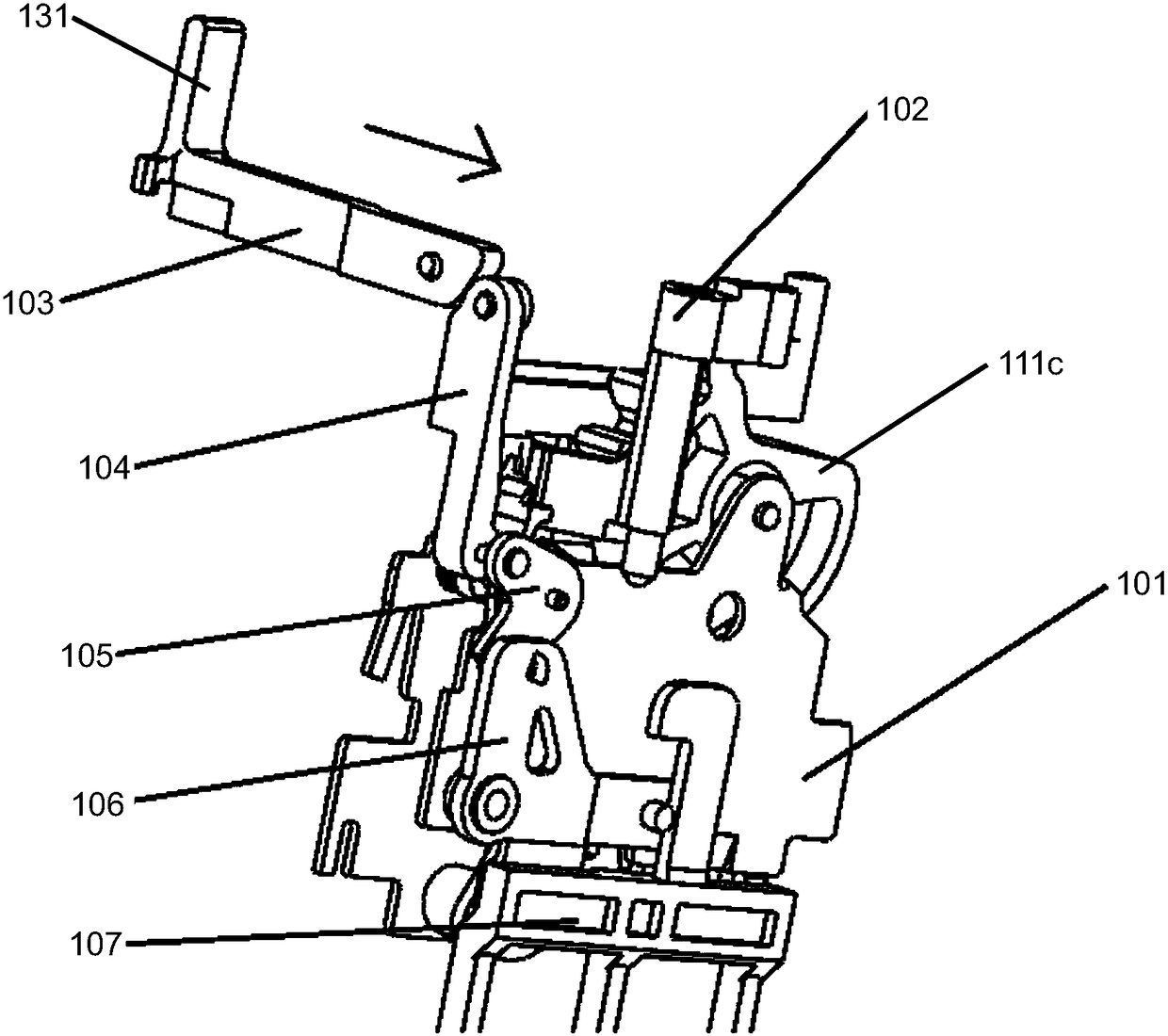
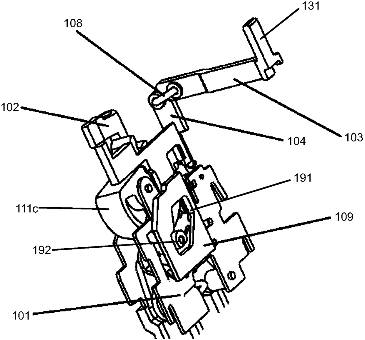
[0025] refer to figure 2 as shown, figure 2 A partial structural diagram of the auxiliary mechanism is disclosed, showing the structure of the front of the main body of the operating mechanism. As shown in the figure, a first push rod 103, a second push rod 104, a U-shaped rod 108, a rotating member 105, a lever 106 and a pull rod 107 are arranged on the front ...


PUM


Abstract

An auxiliary means for an operating mechanism; the auxiliary means is connected to a body (101) of the operating mechanism, and comprises: a trigger assembly, a linkage assembly and a reset assembly. The trigger assembly receives a trigger signal. The linkage assembly is connected to the trigger assembly, and the linkage assembly passes the trigger signal to the body of the operating mechanism so as to trip the body of the operating mechanism. The reset assembly is connected to the linkage assembly, and the reset assembly generates a reset signal, such that the linkage assembly passes the reset signal so as to reset the auxiliary means of the operating mechanism. By using a simple structure thereof and by effectively utilizing the original operating characteristics of the operating mechanism, the auxiliary means of the operating mechanism may achieve breaking, closing, tripping, resetting and isolating functions, as well as implement said functions by using different locations of an operating handle and different positions of a tripping and isolation button, thereby obtaining clear instructions. By reusing structural parts, the present invention not only saves costs, but also avoids multiple connection of a modular structure, thus improving reliability of the product.

Description

technical field [0001] The invention relates to the field of low-voltage electrical appliances, more specifically, to switching appliances for low-voltage electrical appliances. Background technique [0002] Control and protection switchgear is a switchgear that can be automatically controlled in addition to manual control, with or without local manual operation devices, and can be connected, loaded and broken under normal conditions including specified operating overload conditions. And it can connect, carry and break the current under the specified abnormal conditions within the specified time, such as short-circuit current, that is, the control and protection switching device integrates the functions of circuit breaker, contactor and thermal relay. [0003] Switching devices with short-circuit protection, such as circuit breakers and motor protectors, usually operate at different positions through the operating mechanism, disconnect and connect the main circuit, and can t...

Claims


Application Information

Patent Timeline
Patent Type & Authority Patents(China)
IPC IPC(8): H01H3/46H01H3/42H01H71/50H01H71/04
CPCH01H3/42H01H3/46
Inventor 郑捷欣奚泓贾峰李思泓黄悲鸣曾萍冯宇刚
Owner SEARI ELECTRIC TECH
Why Eureka
Try Eureka