A line take-up and release device for field line erection

A wire take-up device and line erection technology, which is applied in the direction of overhead lines/cable equipment, etc., can solve problems such as difficult to prevent balance, strained cables, and difficult to place wire reels in a suitable position, so as to avoid weak grip, The effect of increasing friction and avoiding inner wall wear

Active Publication Date: 2020-12-11
PINGDINGSHAN POWER SUPPLY ELECTRIC POWER OF HENAN +1
View PDF2 Cites 0 Cited by
  • Summary
  • Abstract
  • Description
  • Claims
  • Application Information

AI Technical Summary

Problems solved by technology

[0002] For the erection of transmission lines, especially when erecting transmission lines outdoors, due to the complex and changeable outdoor terrain, for transmission lines, it is difficult to place the reel in a suitable position, and it is difficult to prevent balance due to terrain reasons, while the transmission line After the erection is completed, it needs to be tightened to make the wire erection comply with the regulations. The traditional method is to set a winch at the starting end for tension, but this method often causes cable sheath strain, and in order to avoid cable surface strain and cause cable breakage The phenomenon
[0003] The authorized announcement number is CN206922328U, which discloses a cable pay-off device for construction, including a vehicle frame, a support rod arranged on the vehicle frame, a wire reel fixing device, a pay-off reel and a wire reel unwinding device; The side is provided with a telescopic wheel frame; the wheel frame is provided with traveling wheels; one end of the support rod is connected to the frame through the drive assembly; the other end of the support rod is provided with a wire reel fixing device; the pay-off reel is set on the wire reel fixing device ;The wire reel fixing device is provided with a wire reel unwinding device, although it can be moved and adjusted, it still cannot solve the problem of wire retraction and inability to adapt to complex terrain
[0004] In the authorized announcement number CN206384662U, a new type of cable retractable turntable is disclosed, which relates to the field of cable production and includes a drive shaft, a base, a cable reel, a drive motor and a rotating chassis. The drive shaft is vertically arranged on the upper part of the base, and the cable The disc is welded on both sides of the drive shaft. The cable disc includes an upper cable disc and a lower cable disc. The drive motor is arranged above the upper cable disc. The rotating chassis is arranged between the lower cable disc and the base. The drive shaft There is a partition plate in the middle, fixed hooks are provided on the upper cable tray and the lower cable tray, the rotating chassis includes a drive shaft connected by a bearing, circular through holes are evenly distributed on the outer side of the rotating chassis, and the circular There are balls in the through holes, and a braking device is provided on one side of the rotating chassis. The braking device includes a pedal and a brake lever welded to each other. However, the terrain problem has not been solved, the source winding has not been solved, and the realization of The phenomenon of ability to cross difficult terrain

Method used


Image

  • A line take-up and release device for field line erection
  • A line take-up and release device for field line erection
  • A line take-up and release device for field line erection

Examples


Embodiment 1

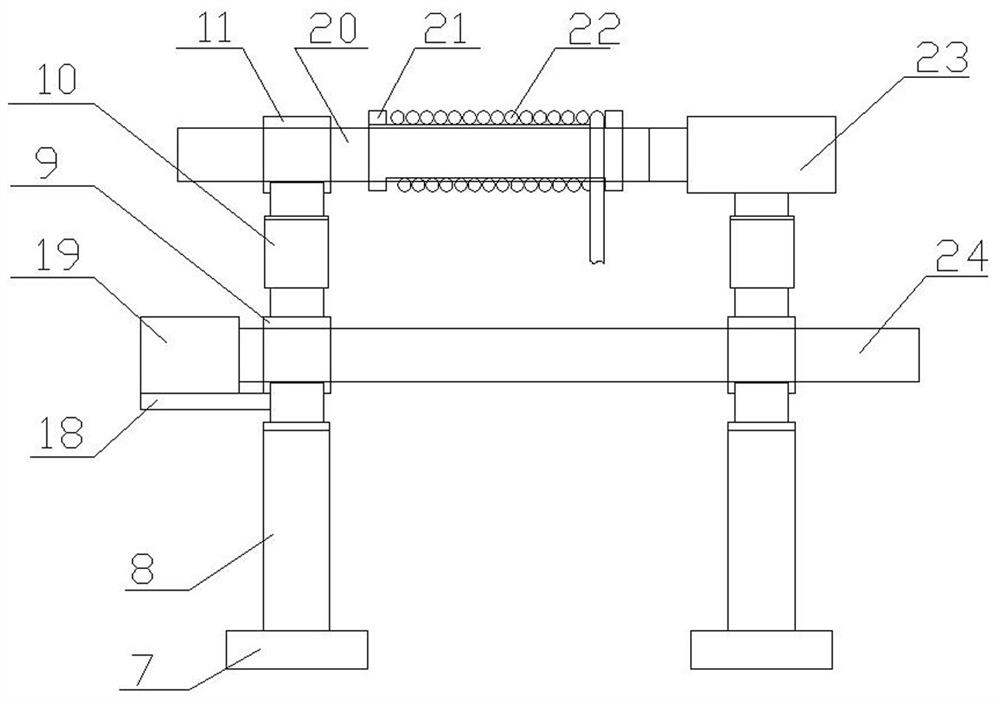
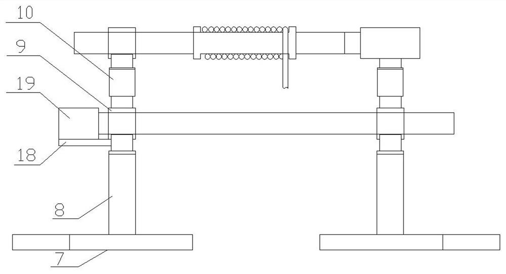
[0034] A retracting and releasing device for field line erection, comprising a mobile base, a retractable support mechanism arranged on the mobile base, a fixing mechanism arranged on the mobile base for fixing, and a fixed mechanism arranged on the mobile base. a traction mechanism on the base and matched with the retractable support mechanism, and a control mechanism arranged on the mobile base for controlling the mobile base, retractable support mechanism, traction mechanism and fixing mechanism;

[0035] Described mobile base comprises main mobile seat 1, is arranged on the main traveling wheel 2 of described main mobile seat 1 both sides, is arranged on two mobile hinge seats on described main mobile seat 1, is arranged on two mobile hinge seats The main support arm 15, the auxiliary traveling wheel 16 arranged at the end of the main support arm 15, and the angle adjustment telescopic rod 17 arranged between the two main support arms.

[0036] The retractable support mech...

Embodiment 2

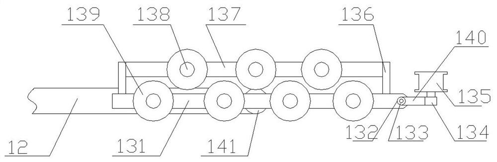
[0043] The difference from Embodiment 1 is that: the fixing mechanism 3 includes a rope module and a fixing rod module arranged on the mobile base;

[0044] The rope module includes a rope arranged on the mobile base, and a steel drill arranged at the end of the rope;

[0045] The fixed rod module includes a telescopic tube 31 arranged on the mobile base, a lock pin hole 32 provided on the telescopic tube 31, a second fixed rod 33 arranged in the telescopic tube 31, and a The threaded hole 37 at the end of the second fixing rod 33, the second threaded rod 34 arranged on the threaded hole 37, the fixing nut 35 arranged on the second threaded rod 34, the fixed nut 35 arranged on the second threaded rod The supporting foot 36 of 34 ends.

Embodiment 3

[0047] The difference between it and the second embodiment is that: the main mobile seat 1 is provided with a counterweight water tank, which can realize the adjustment of the counterweight of the device when filling water, so as to ensure that the transportation will not be inconvenient due to the heavy quality during transportation.


PUM


Abstract

The present invention provides a retracting and releasing device for field line erection, which includes a mobile base, a retractable support mechanism arranged on the mobile base, a fixing mechanism arranged on the mobile base for fixing, and a The traction mechanism on the mobile base and matched with the retractable support mechanism, the overturning mechanism provided on the bottom surface of the mobile base, and the mobile base used to control the 1. The control mechanism of retractable support mechanism, traction mechanism and overturning mechanism; the invention not only adapts to the needs of erecting lines in different terrains, realizes the ability to cross complex terrains, but also can achieve balance and stability, and can also realize the function of source winding.

Description

technical field [0001] The invention relates to the technical field of power transmission line erection equipment, in particular to a line retracting and releasing device for field line erection. Background technique [0002] For the erection of transmission lines, especially when erecting transmission lines outdoors, due to the complex and changeable outdoor terrain, for transmission lines, it is difficult to place the reel in a suitable position, and it is difficult to prevent balance due to terrain reasons, while the transmission line After the erection is completed, it needs to be tightened to make the wire erection comply with the regulations. The traditional method is to set a winch at the starting end for tension, but this method often causes cable sheath strain, and in order to avoid cable surface strain and cause cable breakage The phenomenon. [0003] The authorized announcement number is CN206922328U, which discloses a cable pay-off device for construction, inclu...

Claims


Application Information

Patent Timeline
Patent Type & Authority Patents(China)
IPC IPC(8): B65H75/40B65H75/44H02G1/02
CPCB65H75/40B65H75/4457B65H2701/34H02G1/02
Inventor 王逸超胡军台郭毅鹏肖承仟孙世勇迟成张磊耿新马文恒
Owner PINGDINGSHAN POWER SUPPLY ELECTRIC POWER OF HENAN
Why Eureka
Try Eureka