Ethernet transmission circuit

A technology of transmission circuit and Ethernet, applied in the field of communication, can solve the problems of data transmission throughput drop, damage, increase of equivalent capacitance of transmission circuit, etc.

Active Publication Date: 2016-06-01
COMBA TELECOM SYST CHINA LTD
View PDF7 Cites 3 Cited by
  • Summary
  • Abstract
  • Description
  • Claims
  • Application Information

AI Technical Summary

Problems solved by technology

However, in the current Ethernet communication circuit, the transmission signal will be affected by the DC power supply in the twisted pair and the interference of the external electromagnetic environment, which will greatly increase the possibility that the transmission circuit will be damaged by EMC (ElectroMagneticCompatibility, electromagnetic compatibility) electrostatic pulse, and If the current comm

Method used


Image

  • Ethernet transmission circuit
  • Ethernet transmission circuit
  • Ethernet transmission circuit

Examples


Embodiment Construction

[0036] In order to make the purpose, technical solutions and advantages of the present invention clearer, the present invention will be further described in detail below in conjunction with the accompanying drawings. Obviously, the described embodiments are only some of the embodiments of the present invention, rather than all of them. Based on the embodiments of the present invention, all other embodiments obtained by persons of ordinary skill in the art without making creative efforts belong to the protection scope of the present invention.

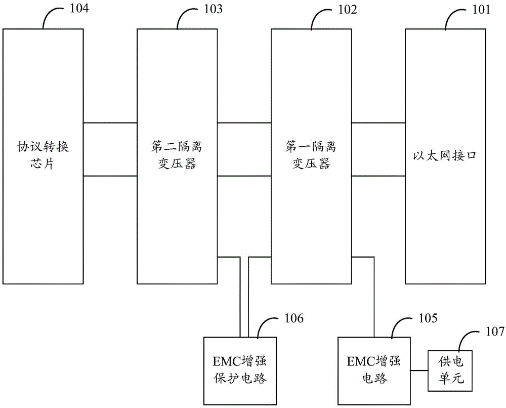
[0037] figure 1 shows the structure of an Ethernet transmission circuit provided by an embodiment of the present invention, such as figure 1 As shown, the Ethernet transmission circuit includes: an Ethernet interface 101, a first isolation transformer 102, a second isolation transformer 103 and a protocol conversion chip 104, the output end of the Ethernet interface 101 is connected to the input end of the first isolation transformer 10...


PUM


Abstract

The invention discloses an Ethernet transmission circuit. The Ethernet transmission circuit comprises an Ethernet interface, a first isolation transformer, a second isolation transformer and a protocol conversion chip; the output end of the Ethernet interface is connected to the input end of the first isolation transformer; the output end of the first isolation transformer is connected to the input end of the second isolation transformer; the output end of the second isolation transformer is connected to the protocol conversion chip; the first isolation transformer is connected to an EMC enhanced circuit with a power supply unit; and an EMC enhanced protection circuit is connected between the first isolation transformer and the second isolation transformer. A differential signal received by the Ethernet interface is enhanced and protected through the EMC enhanced circuit connected onto the first isolation transformer and the EMC enhanced protection circuit between the first isolation transformer and the second isolation transformer, and fed into the protocol conversion chip; therefore, in the event that EMC compatible requirements are satisfied, the error rate for Ethernet communication and transmission is further reduced; the data transmission throughput capacity is increased; and the network delay is reduced.

Description

technical field [0001] The invention relates to the technical field of communication, in particular to an Ethernet transmission circuit. Background technique [0002] In the field of Ethernet communication and transmission, it is currently the most important communication mode to realize the power supply, data and command communication between the control device and the upper computer with the help of Ethernet. However, in the current Ethernet communication circuit, the transmission signal will be affected by the DC power supply in the twisted pair and the interference of the external electromagnetic environment, which will greatly increase the possibility that the transmission circuit will be damaged by EMC (ElectroMagnetic Compatibility, electromagnetic compatibility) electrostatic pulse, and If the current common EMC protection measures are adopted, such as anti-static tubes and filter capacitor networks, the equivalent capacitance to the ground of the transmission circui...

Claims


Application Information

Patent Timeline
IPC IPC(8): H04L1/00H02M1/00
CPCH02M1/00H04L1/00
Inventor 陈观玉李繁白孝涛
Owner COMBA TELECOM SYST CHINA LTD
Why Eureka
Try Eureka