Vehicle Pneumatic Tires

A technology for pneumatic tires and vehicles, applied to vehicle parts, tire parts, tire treads/tread patterns, etc., can solve the problems of high cleaning and maintenance, high clogging, high consumption, etc., and achieve simple methods, snow The effect of optimized ground grip characteristics and reliable positioning

Active Publication Date: 2018-08-21
CONTINENTAL REIFEN DEUTSCHLAND GMBH
View PDF6 Cites 0 Cited by
  • Summary
  • Abstract
  • Description
  • Claims
  • Application Information

AI Technical Summary

Problems solved by technology

However, valves with smaller valve disk diameters tend to be more and more prone to clogging, so that their use in operation is very complex: with high costs for cleaning and maintenance and for automated production more hindrance

Method used


Image

  • Vehicle Pneumatic Tires
  • Vehicle Pneumatic Tires
  • Vehicle Pneumatic Tires

Examples


Embodiment Construction

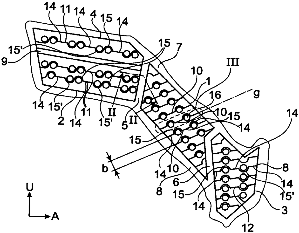
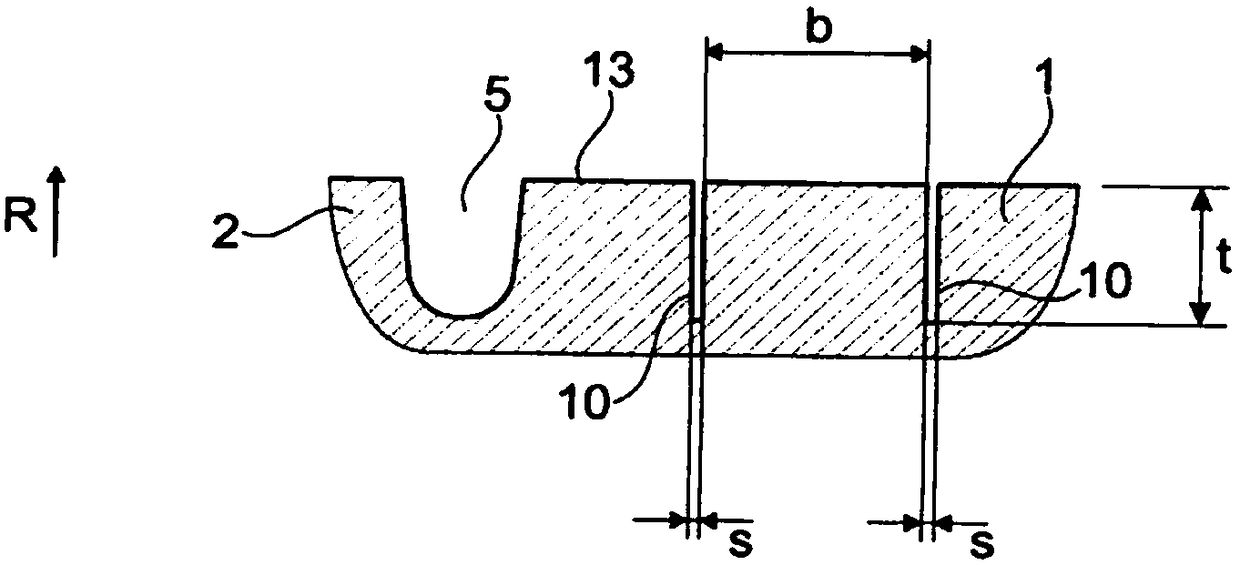
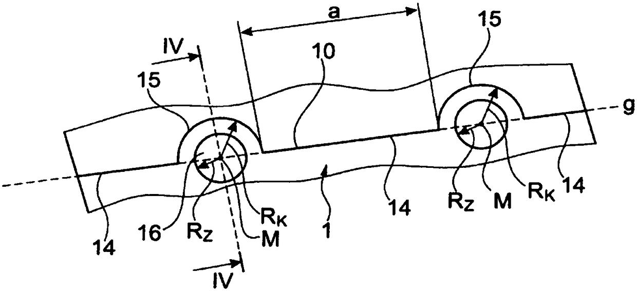
[0025] Figures 1 to 4 Shows the vehicle pneumatic tires for passenger cars (PKW), with the figure 1 A partial view of the tread pattern of the radially raised block units 1 , 2 , 3 and 4 shown in FIG. Spaced out. Here, these block units 1, 3 and 4 are in the circumferential direction U of the vehicle pneumatic tire at figure 1 The direction of rotation shown upwards in the middle is delimited by a transverse groove 7 . These tread block units 1, 2 and 3 are in the circumferential direction U at figure 1 The direction of rotation shown downwards in is correspondingly limited by a transverse groove 8 . The block units 2 and 4 are arranged one behind the other in the circumferential direction and are spaced apart from one another by a transverse groove 9 . The block unit 1 is spaced apart from the block units 2 and 4 in the axial direction A of the vehicle pneumatic tire by a sipe 5 oriented with its main direction of extension in the circumferential direction U. The bl...


PUM


Abstract

The invention relates to a tread pattern for a vehicle tire with radially protruding positive profiles (1) delimited by grooves (5, 6, 7, 8) - such as profiled block elements or profiled ribs - delimited in the radial direction R of the tire by a radially outer surface (13), and with mutually spaced apart, fine incisions (10) formed in the positive profiles (1), the tread pattern being characterised in that fine incisions (10) extending along their main direction of extension in the radially outer surface (13) are formed in the positive profile (1) and have first straight sections (14) - oriented, in particular, in the main direction of extension - and second sections (15) in the shape of circle segment lines,

Description

technical field [0001] The present invention relates to a tread pattern of a pneumatic tire for vehicles, the tread pattern having: radially raised and defined by grooves in reliefs, such as block units or ribs, which are formed in the tire defined by a radially outer surface in the radial direction R of the sipe; and fine cuts formed spaced apart from each other in the sipe. Background technique [0002] Such vehicle pneumatic tires are known. It is known here to form fine cuts running substantially parallel in the blocks of the block rows or in the tread ribs in order to achieve better grip on snow. These thin cuts create an extra grippy edge when rolling. In addition, snow can be pressed into the open fine cuts and thereby further improve the snow grip. It is known here that the thin cuts are formed straight or wave-shaped. [0003] In order to achieve an optimal grip effect on snow, it is desirable here to position the fine cuts in the tread unit in such a way that a...

Claims


Application Information

Patent Timeline
Patent Type & Authority Patents(China)
IPC IPC(8): B60C11/12
Inventor 彼得·博根许茨
Owner CONTINENTAL REIFEN DEUTSCHLAND GMBH
Why Eureka
Try Eureka