Injector and contact elements therefor

A technology of contact elements and injectors, which is applied to electrical components, engine components, fuel injection devices, etc., and can solve the problems of high cost and easy damage

Active Publication Date: 2018-08-17
VTESCO TECH GMBH
View PDF7 Cites 0 Cited by
  • Summary
  • Abstract
  • Description
  • Claims
  • Application Information

AI Technical Summary

Problems solved by technology

Such electrical connections can only be produced with relatively great outlay and ultimately constitute a relatively easily damaged structure
This process cannot be realized in the context of mass production

Method used


Image

  • Injector and contact elements therefor
  • Injector and contact elements therefor

Examples


Embodiment Construction

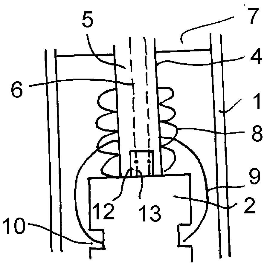
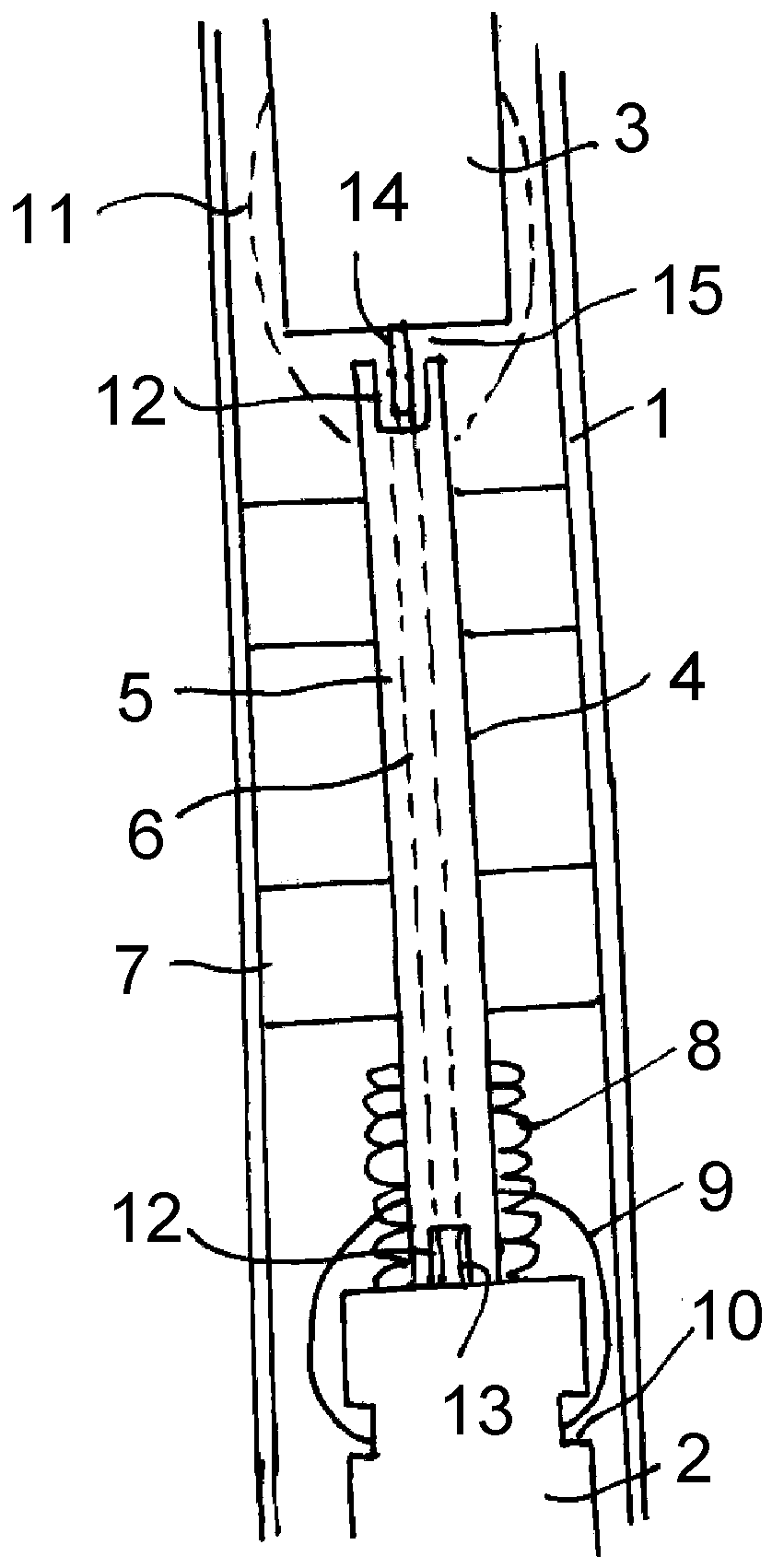
[0024] figure 1 A part of the injector body 1 with the piezoelectric actuator control unit 2 and with the connection plug 3 arranged on the head of the injector body 1 is shown. In order to allow actuation of the piezoelectric actuator control unit 2 , the latter is electrically connected to a connection plug 3 , which in turn is electrically connected to the control unit of the associated injection system of the internal combustion engine. By electrical pulses actuating the piezoelectric actuator control unit 2, the control unit 2 undergoes periodic length extension and contraction, which effect fuel injection via a not shown nozzle mechanism.

[0025] The electrical connection between the piezoelectric actuator control unit and the connection plug 3 is effected via a contact element 4 which has a conductor track 6 integrated into the insulating body 5 . In the exemplary embodiment shown here, as shown, two conductor tracks 6 are provided in the insulating body 5 which protr...


PUM


Abstract

The invention relates to an injector of an injection system of an internal combustion engine. The injector has an injector housing, a piezoelectric actuator control unit, a connection plug on the head of the injector housing, and an electrical connection between the control unit and the connection plug within the injector housing. The electrical connection comprises a contact element with elastic means for supporting the contact element against the control unit or against the connection plug. One end of the contact element bears against the control unit or the connection plug, while the other end is arranged with a corresponding spacing therefrom. In this way, movements and thermal expansions of the control unit can be compensated.

Description

technical field [0001] The invention relates to an injector of an injection system of an internal combustion engine with an injector housing, with a piezo actuator control unit, with a connecting plug on the head of the injector housing, and with an injector housing The electrical connection between the control unit in the body and the connection plug. Background technique [0002] Injectors of this type are known. The piezoelectric actuator control unit is in this case located close to the nozzle unit. For the electrical contacting of the control unit, a connecting plug arranged on the head of the associated injector housing is used. Therefore, it is necessary to provide an electrical connection between the piezoelectric actuator control unit and the connection plug for supplying electrical energy to the control unit. The electrical connection must protect against external vibrations of the internal combustion engine and also against internal vibrations of the control un...

Claims


Application Information

Patent Timeline
Patent Type & Authority Patents(China)
IPC IPC(8): F02M51/06F02M51/00H01L41/053
CPCF02M51/0603F02M51/005H10N30/875
Inventor E.桑夫特莱本M.普勒茨M.西梅特S.柯恩巴赫
Owner VTESCO TECH GMBH
Why Eureka
Try Eureka