Method of manufacturing a rotor for a reluctance motor

A reluctance motor and rotor technology, applied in the manufacture of motor generators, stator/rotor bodies, synchronous motors for single-phase current, etc., can solve the problems of limited number of revolutions, weakened mechanical stability, etc.

Active Publication Date: 2018-02-06
SIEMENS AG
View PDF7 Cites 0 Cited by
  • Summary
  • Abstract
  • Description
  • Claims
  • Application Information

AI Technical Summary

Problems solved by technology

But this leads to a weakening of the mechanical stability, which limits the number of revolutions

Method used


Image

  • Method of manufacturing a rotor for a reluctance motor
  • Method of manufacturing a rotor for a reluctance motor
  • Method of manufacturing a rotor for a reluctance motor

Examples


Embodiment Construction

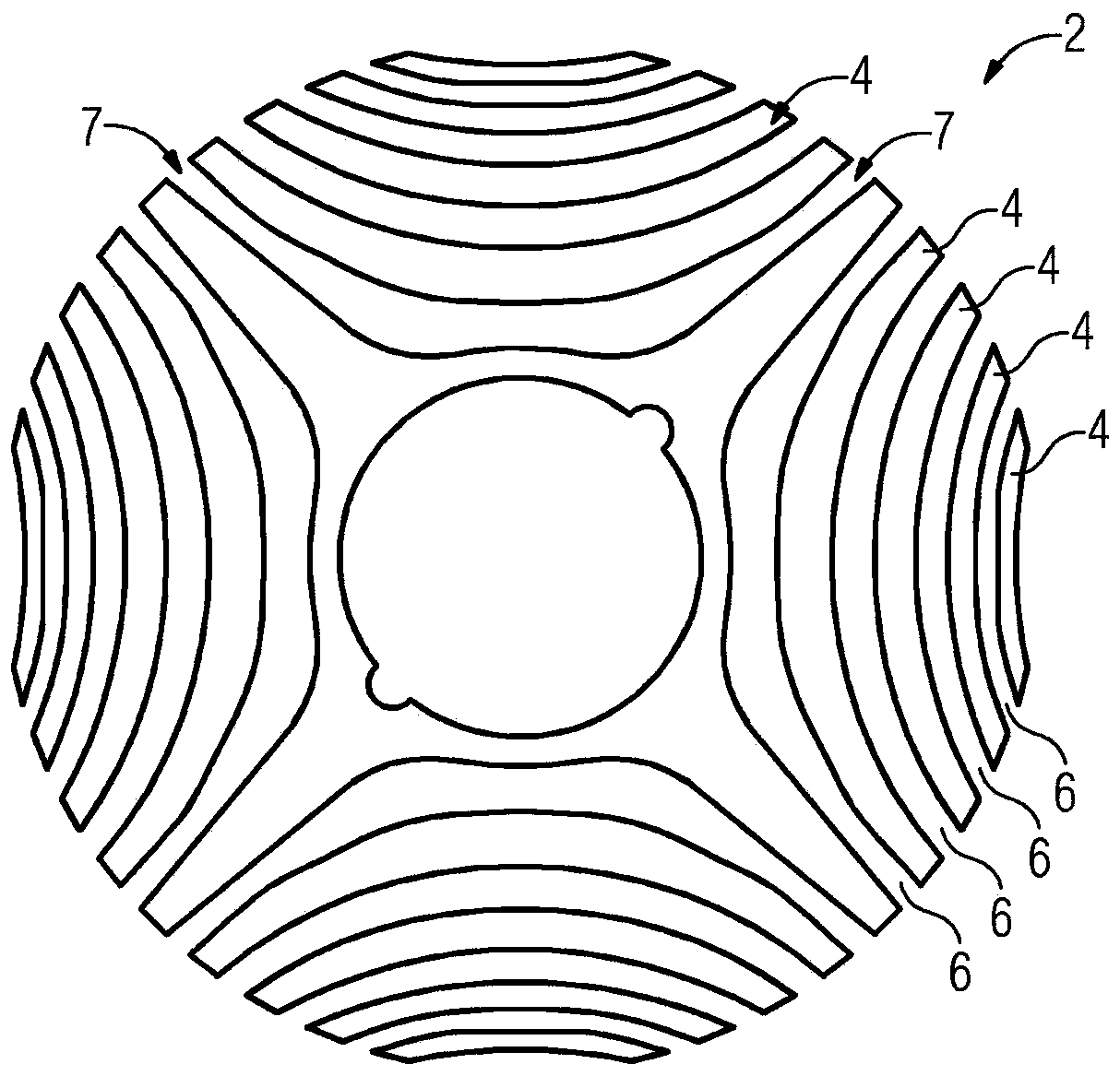
[0035] exist figure 1 Rotor laminations 2 of a rotor 12 produced according to the invention for a reluctance motor 18 , not shown in detail here, are shown in FIG. Such a reluctance motor 18 is Figure 7 Schematically shown in , the reluctance motor is an electric machine comprising a rotor 12 and a stator 20 . The reluctance motor 18 has a housing 22 in which the rotor 12 is rotatably mounted on a shaft 24 . The individual rotor laminations 2 are inserted one after the other on the shaft 24 and in this case form a single lamination stack. In operation, rotor 12 rotates about axis D. Furthermore, the stator 20 is located inside the housing 22 .

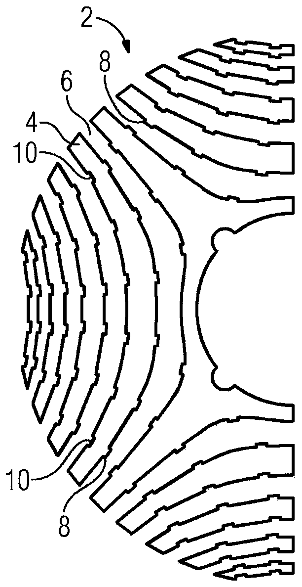
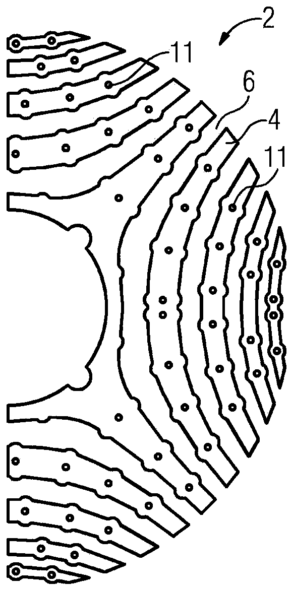
[0036] according to figure 1The rotor lamination 2 has a plurality of magnetic foils 4 made of a material with high magnetic permeability, eg iron. The lamellae are separated from one another by non-magnetic regions, which in the exemplary embodiment shown are arcuate grooves 6 , which are formed in particular by means of a tens...


PUM


Abstract

The invention relates to a rotor (12) having several rotor laminations (2), which are stacked one after the other along an axis of rotation (D), wherein each rotor lamination (2) has a plurality of magnetic fins (4), which are separated from each other by nonmagnetic hollows (6), the nonmagnetic hollows (6) are arcuate and the two ends (7) of the nonmagnetic hollows are open toward an outer circumference (U) of the rotor lamination (2), the hollows (6) of at least some of the rotor laminations (2) are filled with a solid material (16). For the purpose of a simple design and improved functionality of the rotor (12), the stacked rotor laminations (2) are connected to each other only in the direction of the axis of rotation (D) in the assembled state of the rotor (12).

Description

technical field [0001] The present invention relates to a method for manufacturing such a rotor for a reluctance motor. Background technique [0002] An electric machine is a device that converts electrical energy into mechanical energy, especially kinetic energy (motor operation) and / or mechanical energy into electrical energy (generator operation). A rotating electrical machine is an electrical machine in which the stator provides a generally circular opening in which the rotor is rotatably supported. The stator is arranged in a rotationally fixed manner relative to the rotor. The stator and the rotor are coupled by means of the magnetic flux, so that in the operation of the electric motor a force effect is produced which drives the rotor in rotation relative to the stator and in the operation of the generator converts the mechanical energy supplied to the rotor into electrical energy. [0003] A rotor for a reluctance motor is known from US 5 818 140 A. There is descri...

Claims


Application Information

Patent Timeline
Patent Type & Authority Patents(China)
IPC IPC(8): H02K1/24H02K15/12H02K15/02
CPCH02K1/246H02K15/022H02K15/12H02K1/24H02K15/02H02K19/06
Inventor 康拉德·布兰德尔赖纳·格里勒恩贝格尔
Owner SIEMENS AG
Why Eureka
Try Eureka